Welcome to EaseRobot, a cutting-edge autonomous robot designed to revolutionize home automation. This innovative DIY robotics project aims to create a sophisticated house-bot that can navigate and interact with its environment. In this series, we'll delve into the project's details, starting with the concept, hardware selection, and initial software development.
Inspired by the possibilities of modern robotics, EaseRobot is built around a Raspberry Pi 3, Model B, leveraging its processing power and versatility. By harnessing the capabilities of the Robot Operating System (ROS) and Raspberry Pi, we can focus on developing the robot's features rather than building a custom processor board from scratch.
EaseRobot is designed to perform various tasks, including facial recognition, speech synthesis, and autonomous locomotion. Our robot will be equipped with a 7" touchscreen display and a camera module, enabling it to interact with users and navigate its surroundings. With ROS, we can develop and test nodes for the system, simulate the robot's behavior, and refine our code.
In this project, we'll explore various "missions" that EaseRobot can perform, starting with the ability to take messages to specific individuals. We'll break down this mission into smaller design goals, including face recognition, speech synthesis, locomotion control, and navigation. Join us on this exciting journey as we bring EaseRobot to life and explore the possibilities of autonomous robotics.
Getting Started
First installment in a series on a ROS-based Smart Home BotIntroduction
The EaseRobot project is an innovative DIY robotics endeavor aimed at designing and building a sophisticated autonomous house-bot. This article marks the beginning of a series that will delve into the project's details. In this initial part, we'll introduce the concept, select a suitable single-board computer, install ROS (Robot Operating System), and develop the initial control software.
Background
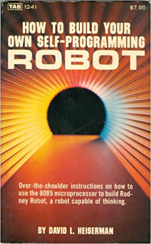
In the late 1970s and early 1980s, I was inspired by two influential books: "How to build your own self-programming robot" by David L. Heiserman and "How to build a computer-controlled robot" by Tod Loofbourrow. The original plan was to design a custom processor board based on a Z80 processor and then build a robot around it. Unfortunately, the project never took off. Fast-forward to today, with the advent of compact boards like the Raspberry Pi and Arduino, creating a home robot has become significantly more accessible, although our expectations of its capabilities have increased dramatically.
As a nod to one of these books, our robot is named EaseRobot.
Unlike in the early 80s, we're fortunate to have a wide range of options available. EaseRobot will be built around a Raspberry Pi 3, Model B with 1GB of RAM, making it easier to focus on the robot's development rather than building a processor board from scratch.
Harnessing the Power of ROS and Raspberry Pi
I'll delve into how I've leveraged ROS in the EaseRobot project, highlighting how I've utilized various ROS tools to test and refine my code. While this isn't a comprehensive ROS tutorial, I'll provide essential ROS terms and concepts to facilitate a smooth read. For in-depth tutorials, I recommend exploring the ROS Wiki.
To begin with, here are some key ROS concepts:
- ROS is a distributed system, enabling robot code to run on multiple machines that communicate over a network.
- A node is a single-purpose executable that performs a specific task.
- Nodes are organized into packages, which are collections of folders and files.
- Nodes can be written in multiple languages, including C++ and Python, which we'll use in this project.
- Nodes communicate with each other using Topics, which are one-way streams of data.
- Topics are instances of Messages, which are data structures that can be standard or user-defined.
- Nodes can also communicate using Services, a server/client blocking protocol, and Actions, a non-blocking goal-oriented task protocol.
- The master node, roscore, is the central hub that all other nodes register with, ensuring seamless communication.
- ROS utilizes a catkin build system and provides various tools for examining and simulating the system.
- Individual nodes can be run using the rosrun command or the launch tool, which enables starting multiple nodes from a single command terminal.
- ROS includes a parameter server, allowing nodes to store and retrieve parameters during runtime.
With the decision to use a Raspberry Pi 3 as the main processor and ROS, the first step is to install ROS on the Pi. To simplify the process, I'll use an Ubuntu image for the Raspberry Pi that includes ROS, available for free from the Ubiquity Robotics website. This image features the Kinetic version of ROS and includes useful ROS packages, such as the raspicam_node for accessing the Raspberry Pi camera.
Other Raspberry Pi peripherals I plan to use in the EaseRobot project include:
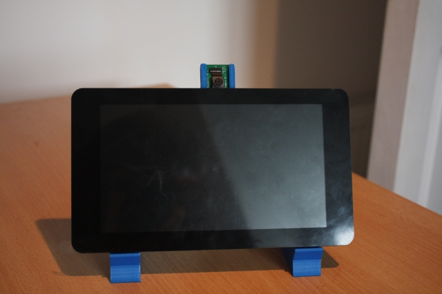
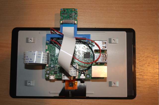
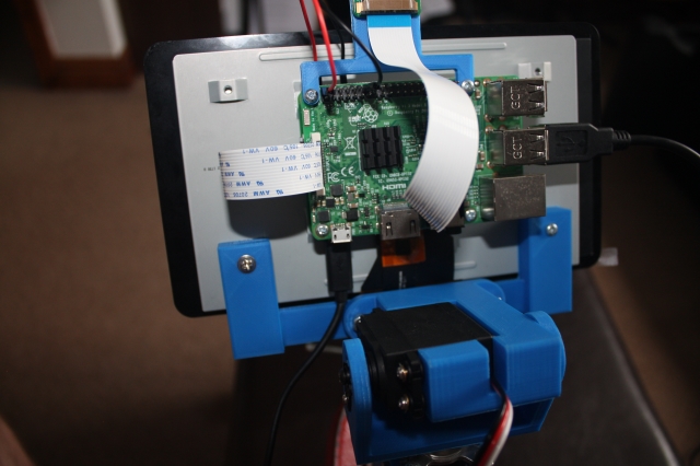
- 7" Touchscreen Display
- Camera Module V2
The display will be used to convey status information, web content, and an animated robot face to the user. The camera will serve as the robot's eyes, initially used for facial recognition.
The following images show the 7" display with the Raspberry Pi and camera mounted on the rear of the screen. The camera is mounted using a 3D printed bracket, with the stl file available in the 3D print zip file included with this article.
As ROS can run across a distributed network, I've also installed ROS on an Ubuntu desktop. This desktop PC will be used to develop nodes for the system, run ROS tools to test the code, and simulate the robot's behavior.
Robotic Missions
To define the requirements for the EaseRobot project, I'll outline some "missions" that I'd like EaseRobot to perform. Inspired by the article "Let's build a robot!", one of the tasks I'd like EaseRobot to accomplish is:
Take a message to... - Since EaseRobot will have the ability to recognize family members, how about the ability to make it the'message taker and reminder'? I could say 'EaseRobot, remind (PersonName) to pick me up from the station at 6pm'. Then, even if that household member had their phone turned off or were listening to loud music, EaseRobot could navigate through the house, find the person, and deliver the message.
This sounds like a great starting point and will be our first mission. I'll modify it slightly, though. What if you could access EaseRobot using a web browser to control and set missions?
Let's break down the "Take a message to..." mission into several smaller design goals that can be worked on and completed individually. The design goals for this mission will be:
Design Goal 1: To be able to look around using the camera, search for faces, attempt to identify any people seen, and display a message for any identified.
Design Goal 2: Facial expressions and speech synthesis. EaseRobot will need to be able to deliver the message.
Design Goal 3: Locomotion controlled by a remote keyboard and/or joystick.
Design Goal 4: Addition of a laser ranger finder or similar ranging sensor used to aid navigation.
Design Goal 5: Autonomous locomotion.
Design Goal 6: Task assignment and completion notification.
That's quite a list of things to accomplish for what seems like a simple mission for a robot.
Mission 1, Design Goal 1
To accomplish this design goal, we will need to:
- Control the head/camera using RC servos for pan/tilt movement.
- Access images from the Raspberry Pi Camera.
- Detect and recognize faces.
- Control the order of these actions.
For the remainder of this first article, I'll concentrate on the pan/tilt control of the head/camera.
To control the head/camera, we need a pan and tilt device which will require two RC servos. I'm also going to include a second pan/tilt device for future expansion. We therefore require four PWM outputs to control the servos. The Raspberry Pi only has one hardware PWM, and although we could make use of software PWMs, I'm going to avoid that overhead by passing control of the servos off to a second board.
We could use a purpose-built board like the one available from PiBorg, the UltraBorg. Using this board, you can connect up to four servos and four HC-SR04 ultrasonic devices to the Raspberry Pi using an I2C bus. However, since I have a number of Arduino Nano's available from a previous project, I'm going to make use of one of those.
This is also going to be our first of many examples in taking advantage of work already carried out by the ROS community, allowing us to concentrate on the robot application. To attach to the ROS-like node which will be running on the Arduino, we are going to use a package that includes a node for communicating with the Arduino over the serial port and an Arduino library for use in the Arduino sketch. This package documentation is available on the ROS Wiki website rosserial_arduino.
To utilize this package, we'll need to install it on the ROS target and integrate the library into the Arduino IDE environment. Additionally, we'll need to rebuild the Arduino library if we define custom ROS messages (which we will). The rosserial Arduino tutorials provide a comprehensive guide on how to accomplish this and more.
To control the position of each servo comprising the pan/tilt devices, we'll develop a ROS package with a node that takes pan/tilt demand messages and converts them into individual position messages sent to the Arduino. The first message will specify which joints to move and their required positions. The second message, sent to the Arduino, will contain an index value indicating which of the four servos to move and the angle to which it should be moved. By breaking down this functionality, the Arduino sketch only needs to understand servo control, making it reusable for other servo applications. Note that in Arduino programming, the code running on the Arduino is referred to as a sketch, which I'll continue to use throughout this tutorial.
For the initial message, which specifies the joint positions, we'll utilize the ROS predefined message sensor_msgs/JointState. You can find the documentation for this message type here. As per ROS standards, the position units are radians, so our node will need to convert the position to degrees for the Arduino. The message also includes several fields that we won't be using. Although using this message type might seem excessive, adhering to ROS standards and leveraging existing message types will enable us to tap into valuable ROS tools later in the project.
The second message, which identifies the servo to move and the angle in degrees, will be a custom message to avoid unnecessary overhead in the Arduino sketch.
We could include the definition of our custom messages in the pan-tilt package, but to promote reuse, we'll create a separate package for the message definitions.
To complete the pan-tilt functionality, we'll develop two ROS packages and a ROS-style Arduino sketch.
We'll call the first package servo_msgs, which will define our custom message. Upon building, it will generate.h files for use by C++ code and automatically create Python scripts. We'll also recompile the Arduino library to produce.h files that will be used by our sketch.
The files comprising this first package are available in the servo_msgs folder. The root of this folder contains a readme file documenting the package, along with two files that are required in every ROS package: CmakeList.txt and package.xml. You can find information about these files in the tutorial on creating ROS packages.
The msg folder within the package contains the definition file for our message, servo_array.msg:
# index references the servo that the angle is for, e.g. 0, 1, 2 or 3
# angle is the angle to set the servo to
uint8 index
uint16 angle
Imagine this as a structured data format, similar to C. This message will be transmitted as a ROS topic to the Arduino, containing two essential elements: the index, which specifies the servo to be moved, and the angle, which defines the degree to which the servo should be rotated.
This concludes our first straightforward ROS package. Our second package is the pan_tilt package, located in the pan_tilt folder, which comprises executable code that will form the pan_tilt_node.
The root folder of this package includes a documentation file, as well as the CmakeList.txt and package.xml files. This package features several subfolders, which I'll briefly outline. The config folder contains the config.yaml file, which will be utilized by the launch file (discussed below) to set specific parameters in the parameter server. This enables us to configure the system without requiring code recompilation.
# In Rodney index0 is for the head and index 1 is spare
servo:
  index0:
    pan:
      servo: 0
      joint_name: 'head_pan'
    tilt:
      servo: 1
      flip_rotation: true
      max: 0.349066
      min: -1.39626
      joint_name: 'head_tilt'
  index1:
    pan:
      servo: 2
    tilt:
      servo: 3
In this configuration file, index0 specifies parameters for the head pan and tilt device, while index1 corresponds to the second pan and tilt device. The parameters are defined as follows:
- servo: identifies the servo responsible for the joint
- joint_name: specifies the name of the joint in the joint_state message
- flip_rotation: (explained below)
- max and min: defined in radians, these values restrict the joint's travel range
According to ROS convention, joints follow the right-hand rule, increasing their value in an anticlockwise direction around a positive axis. However, in Rodney's construction, the head tilt servo is mounted to follow the left-hand rule. By setting flip_rotation to true, our system can adhere to the convention while ensuring the pan_tilt_node passes correct values to the Arduino for the servo's orientation.
The cfg folder contains the pan_tilt.cfg file, which is used by the dynamic reconfiguration server to adjust servo trim on the fly. As seen, this file is a Python script.
#!/usr/bin/env python
PACKAGE = "pan_tilt"

from dynamic_reconfigure.parameter_generator_catkin import *

gen = ParameterGenerator()

gen.add("index0_pan_trim", int_t, 0, "Index 0 - Pan Trim", 0, -45, 45)
gen.add("index0_tilt_trim", int_t, 0, "Index 0 - Tilt Trim", 0, -45, 45)
gen.add("index1_pan_trim", int_t, 0, "Index 1 - Pan Trim", 0, -45, 45)
gen.add("index1_tilt_trim", int_t, 0, "Index 1 - Tilt Trim", 0, -45, 45)

exit(gen.generate(PACKAGE, "pan_tilt_node", "PanTilt"))
For a comprehensive understanding of the dynamic reconfiguration server, refer to the ROS Wiki section on dynamic reconfiguration. In our file, we add four parameters, one for each servo, with default values set to zero and minimum/maximum values set to -45 and 45, respectively.
The launch folder contains launch files that enable us to load configuration files and start all nodes that comprise a system. Our folder includes a pan_tilt_test.launch file for testing the pan/tilt part of the Rodney system. This is an XML-formatted file.
<?xml version="1.0"?>
<launch>
<rosparam command="load" file="$(find pan_tilt)/config/config.yaml" />
<node pkg="pan_tilt" type="pan_tilt_node" name="pan_tilt_node" output="screen" />
<node pkg="rosserial_python" type="serial_node.py" name="serial_node"
output="screen" args="/dev/ttyUSB0" />
</launch>
For a complete understanding of launch files, refer to the ROS Wiki section on launch files. Our launch file first loads the config file.
<rosparam command="load" file="$(find pan_tilt)/config/config.yaml" />
The next tag executes our pan_tilt_node, directing logging messages to the terminal.
<node pkg="pan_tilt" type="pan_tilt_node" name="pan_tilt_node" output="screen" />
The final tag runs the rosserial node, which communicates with the Arduino, selecting the serial port connected to the Arduino.
<node pkg="rosserial_python" type="serial_node.py" name="serial_node"
output="screen" args="/dev/ttyUSB0" />
The remaining folders, include and src, contain the C++ code for the package. Our package has one C++ class, PanTiltNode, and a main routine within the pan_tilt_node.cpp file.
The main routine initializes our node, creates an instance of our class, passes a callback function to the dynamic reconfiguration server, and hands control to ROS spin, which handles incoming and outgoing topics.
int main(int argc, char **argv)
{
ros::init(argc, argv, "pan_tilt_node");

PanTiltNode *pan_tiltnode = new PanTiltNode();

dynamic_reconfigure::Server<pan_tilt::PanTiltConfig> server;
dynamic_reconfigure::Server<pan_tilt::PanTiltConfig>::CallbackType f;

f = boost::bind(&PanTiltNode::reconfCallback, pan_tiltnode, _1, _2);
server.setCallback(f);

std::string node_name = ros::this_node::getName();
ROS_INFO("%s started", node_name.c_str());
ros::spin();
return 0;

}
The constructor for our class loads parameters from the parameter server setup by our configuration file.
// Constructor
PanTiltNode::PanTiltNode()
{
double max_radians;
double min_radians;
int temp;

/* Get any parameters from server which will not change after startup.
 * Defaults used if parameter is not in the parameter server
 */

// Which servo is used for what
n_.param("/servo/index0/pan/servo",  pan_servo_[0],  0);
n_.param("/servo/index0/tilt/servo", tilt_servo_[0], 1);
n_.param("/servo/index1/pan/servo",  pan_servo_[1],  2);
n_.param("/servo/index1/tilt/servo", tilt_servo_[1], 3);

// Check for any servos mounted the opposite rotation of the right-hand rule
n_.param("/servo/index0/pan/flip_rotation", pan_flip_rotation_[0], false);
n_.param("/servo/index0/tilt/flip_rotation", tilt_flip_rotation_[0], false);
n_.param("/servo/index1/pan/flip_rotation", pan_flip_rotation_[1], false);
n_.param("/servo/index1/tilt/flip_rotation", tilt_flip_rotation_[1], false);

/* Maximum and Minimum ranges. Values stored on parameter server in
 * radians and RH rule as per ROS standard. These need converting
 * to degrees and may need flipping.
 */
n_.param("/servo/index0/pan/max", max_radians, M_PI/2.0);
n_.param("/servo/index0/pan/min", min_radians, -(M_PI/2.0));
pan_max_[0] = (int)signedRadianToServoDegrees(max_radians, pan_flip_rotation_[0]);
pan_min_[0] = (int)signedRadianToServoDegrees(min_radians, pan_flip_rotation_[0]);
if(true == pan_flip_rotation_[0])
{
    temp = pan_max_[0];
    pan_max_[0] = pan_min_[0];
    pan_min_[0] = temp;
}

//... (rest of the code)

// Joint names
n_.param<std::string>("/servo/index0/pan/joint_name",
                       pan_joint_names_[0], "reserved_pan0");
n_.param<std::string>("/servo/index0/tilt/joint_name",
                       tilt_joint_names_[0], "reserved_tilt0");
n_.param<std::string>("/servo/index1/pan/joint_name",
                       pan_joint_names_[1], "reserved_pan1");
n_.param<std::string>("/servo/index1/tilt/joint_name",
                       tilt_joint_names_[1], "reserved_tilt1");

first_index0_msg_received_ = false;
first_index1_msg_received_ = false;

// Published topic is latched
servo_array_pub_ = n_.advertise<servo_msgs::servo_array>("/servo", 10, true);

// Subscribe to topic
joint_state_sub_ = n_.subscribe("/pan_tilt_node/joints",
                                 10, &PanTiltNode::panTiltCB, this);

}
The calls to param read the parameter from the server if it is available, otherwise, the default value is used.
n_.param("/servo/index0/pan_servo", pan_servo_[0], 0);
The last two lines of the constructor subscribe to the topic and advertise which topics our node will be publishing. The subscribe call is passed the callback function to be called when the topic arrives.
Our callback function is called panTiltCB.
// Callback to move the joints
void PanTiltNode::panTiltCB(const sensor_msgs::JointState& joint)
{
bool index0 = false;
bool index1 = false;

/* Search the list of joint names in the message. Although we expect pan/tilt
 * values for one device, a JointState message may contain data for one joint
 * or all four joints. The position (rotation) values are signed radians and
 * follow the right-hand rule. Values to be converted from signed radians to
 * degrees and for the servo orientation. Pan/tilt values are also stored in
 * case we change the trim.
 */
for (unsigned int i = 0; i < joint.name.size(); i++)
{
    // Is it one of the pan or tilt joints
    if(pan_joint_names_[0] == joint.name[i])
    {
        // Index 0 pan
        index0_pan_ = (int)signedRadianToServoDegrees
                      (joint.position[i], pan_flip_rotation_[0]);
        index0 = true;
    }
    else if(pan_joint_names_[1] == joint.name[i])
    {
        // Index 1 pan
        index1_pan_ = (int)signedRadianToServoDegrees
                      (joint.position[i], pan_flip_rotation_[1]);
        index1 = true;
    }
    else if(tilt_joint_names_[0] == joint.name[i])
    {
        // Index 0 tilt
        index0_tilt_ = (int)signedRadianToServoDegrees
                       (joint.position[i], tilt_flip_rotation_[0]);
        index0 = true;
    }
    else if (tilt_joint_names_[1] == joint.name[i])
    {
        // Index 1 tilt
        index1_tilt_ = (int)signedRadianToServoDegrees
                       (joint.position[i], tilt_flip_rotation_[1]);
        index1 = true;
    }
}

if(index0 == true)
{
    first_index0_msg_received_ = true;
    movePanTilt(index0_pan_, index0_tilt_, index0_pan_trim_, index0_tilt_trim_, 0);
}

if(index1 == true)
{
    first_index1_msg_received_ = true;
    movePanTilt(index1_pan_, index1_tilt_, index1_pan_trim_, index0_tilt_trim_, 1);
}

}
The callback function iterates through the names in the received message, searching for a known joint name. If a name is found, the associated position value is converted from the ROS standard and orientation to a value representing degrees on the servo using the signedRadianToServoDegrees helper function.
The callback then calls the function movePanTilt. This function adds in the trim offset for the relevant pan and tilt servos, checks if the range should be limited, and then publishes the two messages with the servo index and position. The two messages published are of the same type, one is for the relevant pan servo and the second is for the relevant tilt servo.
void PanTiltNode::movePanTilt(int pan_value, int tilt_value,
int pan_trim, int tilt_trim, int index)
{
int pan;
int tilt;
servo_msgs::servo_array servo;

pan = pan_trim + pan_value;
tilt = tilt_trim + tilt_value;

pan = checkMaxMin(pan, pan_max_[index], pan_min_[index]);
tilt = checkMaxMin(tilt, tilt_max_[index], tilt_min_[index]);

// Send message for pan position
servo.index = (unsigned int)pan_servo_[index];
servo.angle = (unsigned int)pan;
servo_array_pub_.publish(servo);

// Send message for tilt position
servo.index = (unsigned int)tilt_servo_[index];
servo.angle = (unsigned int)tilt;
servo_array_pub_.publish(servo);

}
There are two helper functions. The first is used to check for the max/min range.
int PanTiltNode::checkMaxMin(int current_value, int max, int min)
{
int value = current_value;

if (value > max)
{
    value = max;
}

if (value < min)
{
    value = min;
}

return (value);

}
The second helper function is used to convert the ROS standard units and orientation for rotation to those required by the servo.
// Converts a signed radian value to servo degrees. 0 radians is 90 degrees.
double PanTiltNode::signedRadianToServoDegrees(double rad, bool flip_rotation)
{
double retVal;

if(true == flip_rotation)
{
    retVal = ((-rad/(2.0*M_PI))*360.0)+90.0;
}
else
{
    retVal = ((rad/(2.0*M_PI))*360.0)+90.0;
}

return retVal;

}
The dynamic parameter server callback stores each of the trim parameters and then makes two calls to movePanTilt, one for each pan/tilt device, with the last position value and the latest trim values.
// This callback is for when the dynamic configuration parameters change
void PanTiltNode::reconfCallback(pan_tilt::PanTiltConfig &config, uint32_t level)
{
index0_pan_trim_ = config.index0_pan_trim;
index0_tilt_trim_ = config.index0_tilt_trim;
index1_pan_trim_ = config.index1_pan_trim;
index1_tilt_trim_ = config.index1_tilt_trim;

// We don't want to send a message following a call here unless we have received
// a position message. Otherwise the trim value will be taken for an actual position.
if(first_index0_msg_received_ == true)
{
    // Send new messages with new trim values
    movePanTilt(index0_pan_, index0_tilt_, index0_pan_trim_, index0_tilt_trim_, 0);
}

if(first_index1_msg_received_ == true)
{
    movePanTilt(index1_pan_, index1_tilt_, index1_pan_trim_, index1_tilt_trim_, 1);
}

}
The pan_tilt_node.h file contains the definitions for our PanTiltNode class.
Having completed the pan tilt package, the last coding task is to write the Arduino sketch. The sketch contains many of the elements used in the pan/tilt node. Our sketch is based on the servo tutorial for rosserial, but we need to modify it to access more than one servo and subscribe to our user-defined message.
Each Arduino sketch includes a setup and loop procedure. Our setup procedure initializes the node and subscribes to the servo topic. The remainder of the setup procedure attaches the pins 9, 6, 5, and 10 to the four instances of Servo.
The loop procedure simply calls spinOnce and then delays for 1ms. The call to spinOnce will handle the receipt of the topic.
Attached to the receipt of the servo topic is the callback function servo_cb. This function will be called each time the servo topic message is received, and it then simply adjusts the PWM output for the indexed servo.
/*

Based on the rosserial Servo Control Example
This version controls up to four RC Servos
The node subscribes to the servo topic and acts on a rodney_msgs::servo_array message.
This message contains two elements, index and angle. Index references the servos 0-3, and
angle is the angle to set the servo to 0-180.
D5 -> PWM servo indexed 2
D6 -> PWM servo indexed 1
D9 -> PWM servo indexed 0
D10 -> PWM servo indexed 3
*/
#if (ARDUINO >= 100)
#include <Arduino.h>
#else
#include <WProgram.h>
#endif

#include <Servo.h>
#include <ros.h>
#include <servo_msgs/servo_array.h>

/* Define the PWM pins that the servos are connected to */
#define SERVO_0 9
#define SERVO_1 6
#define SERVO_2 5
#define SERVO_3 10

ros::NodeHandle nh;

Servo servo0;
Servo servo1;
Servo servo2;
Servo servo3;

void servo_cb( const servo_msgs::servo_array& cmd_msg)
{
/* Which servo to drive */
switch(cmd_msg.index)
{
case 0:
nh.logdebug("Servo 0 ");
servo0.write(cmd_msg.angle); //set servo 0 angle, should be from 0-180
break;

case 1:
  nh.logdebug("Servo 1 ");
  servo1.write(cmd_msg.angle); //set servo 1 angle, should be from 0-180
  break;

case 2:
  nh.logdebug("Servo 2 ");
  servo2.write(cmd_msg.angle); //set servo 2 angle, should be from 0-180
  break;

case 3:
  nh.logdebug("Servo 3 ");
  servo3.write(cmd_msg.angle); //set servo 3 angle, should be from 0-180
  break;

default:
  nh.logdebug("No Servo");
  break;

}
}

ros::Subscriber<servo_msgs::servo_array> sub("servo", servo_cb);

void setup()
{
nh.initNode();
nh.subscribe(sub);

servo0.attach(SERVO_0); //attach it to the pin
servo1.attach(SERVO_1);
servo2.attach(SERVO_2);
servo3.attach(SERVO_3);

// Defaults
servo0.write(90);
servo1.write(120);
}

void loop(){
nh.spinOnce();
delay(1);
}
Implementing the Code
Before we can compile the sketch and program the Arduino, we need to build our ROS packages and recompile the ROS Arduino library. This step is crucial to make our user-defined message, servo_array, available in the Arduino IDE.
For this tutorial, I will be using a Linux workstation to run the Arduino IDE. I will build our packages on both the workstation and the Raspberry Pi. Although we are not utilizing any dedicated Raspberry Pi hardware at this stage, you can opt to run the nodes entirely on a workstation. I will run the nodes on the Raspberry Pi and run the test tools on the workstation, but you can choose to run the test tools on the Pi if you prefer. To distinguish between the Pi and the workstation in the instructions below, I have created a directory (workspace) called "ease_robot_ws" on the Pi and "test_ws" on the workstation.
Building the ROS Packages on the Workstation
ROS employs the catkin build system. To begin, we will create a catkin workspace and initialize the workspace. In a command terminal, enter the following commands:
$ mkdir -p ~/test_ws/src
$ cd ~/test_ws/
$ catkin_make
Next, copy the two package folders, pan_tilt and servo_msgs, into the ~/test_ws/src folder and build the code using the following commands:
$ cd ~/test_ws/
$ catkin_make
Verify that the build completes without any errors.
Building the Arduino ROS Library
I have the Arduino IDE installed on the workstation, which created an Arduino folder in my home directory containing a subdirectory "libraries". Note that when regenerating the library, you must delete the ros_lib folder using "rm -rf ros_lib" from within the "libraries" directory.
Use the following commands to build the ros_lib library:
$ source ~/test_ws/devel/setup.bash
$ cd ~/Arduino/libraries
$ rm -rf ros_lib
$ rosrun rosserial_arduino make_libraries.py.
Verify that the build completes without any errors and check that the servo_array.h file was created in the ~/Arduino/libraries/ros_lib/servo_msgs folder.
Building the servo Sketch and Programming the Arduino
Copy the ease_robot_control folder to the ~/Arduino/Projects folder. Start the Arduino IDE and open the ease_robot_control.ino file. From the Tools->Board menu, select the Arduino board you are using. In my case, it's the Nano. From the Tools->Processor menu, select the processor. In my case, it's the ATmega328P (Old Bootloader).
Build the sketch and check for any errors.
To program the Arduino, connect the device to a workstation USB port. In the IDE, from the Tools->Port menu, select the serial port that the Arduino is connected to. In my case, it's /dev/ttyUSB0.
Next, upload the sketch to the Arduino and verify that there are no errors reported.
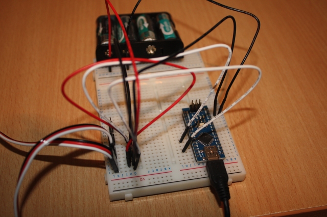
Arduino Circuit
When building EaseRobot, we need to consider power management. For now, I will power the Arduino using the USB port of the Raspberry Pi, while the servos will be powered from 4xAA rechargeable batteries. Below is a test circuit that illustrates the servo connections and power supply to the servos.
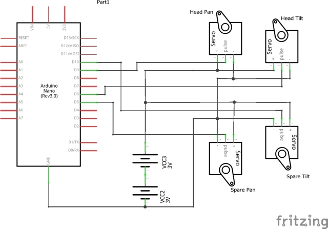
To test the software, I will build the circuit on a breadboard and connect only the servos for the head pan and tilt device.
Building the ROS Packages on the Raspberry Pi
Create a catkin workspace and initialize the workspace. In a command terminal, enter the following commands:
$ mkdir -p ~/ease_robot_ws/src
$ cd ~/ease_robot_ws/
$ catkin_make
Copy the two package folders, pan_tilt and servo_msgs, into the ~/ease_robot_ws/src folder and then build the code using the following commands:
$ cd ~/ease_robot_ws/
$ catkin_make
Verify that the build completes without any errors.
Tip
When running ROS code and tools on a workstation and the Raspberry Pi, you may encounter repetitive typing of commands in multiple terminals. To simplify this process, I have included the full commands to type below. Here are a few tips to save you from excessive typing:
On the Raspberry Pi, to avoid typing "source devel/setup.bash", I have added it to the.bashrc file.
$ cd ~/
$ nano.bashrc
Then add "source /home/ubuntu/ease_robot_ws/devel/setup.bash" to the end of the file, save, and exit.
When running test code and tools on the workstation, it needs to know where the ROS master is located. I have added the following to the.bashrc file for the workstation:
alias ease_robot='source ~/test_ws/devel/setup.bash;
export ROS_MASTER_URI=http://ubiquityrobot:11311'
By simply typing "ease_robot" at a terminal, the two commands are executed, saving you from repetitive typing.
Running the Code
Now that we have set up our code, we are ready to run it. With the Arduino connected to a USB port of the Raspberry Pi, use the launch file to start the nodes with the following commands. If no master node is running in the system, the launch command will also launch the master node, roscore.
$ cd ~/ease_robot_ws/
$ source devel/setup.bash
$ roslaunch pan_tilt pan_tilt_test.launch
In the terminal, you should see:
- A list of parameters now in the parameter server
- A list of the nodes, which should show pan_tilt_node and serial_node
- The address of the master
- The starting of the two nodes
- Log information from our code
We can now use some of the ROS tools to examine, interact, and test the system.
To test that the expected nodes are running and connected using the topics, open a command terminal on the workstation and type the following command:
$ cd ~/test_ws
$ source devel/setup.bash
If you launched the nodes on one device, for example, the Raspberry Pi, and want to run the tools on a second device, you need to tell the second device where to find the master. In the same terminal, type:
$ export ROS_MASTER_URI=http://ubiquityrobot:11311
Now, in the same terminal, start the graph tool:
$ rqt_graph
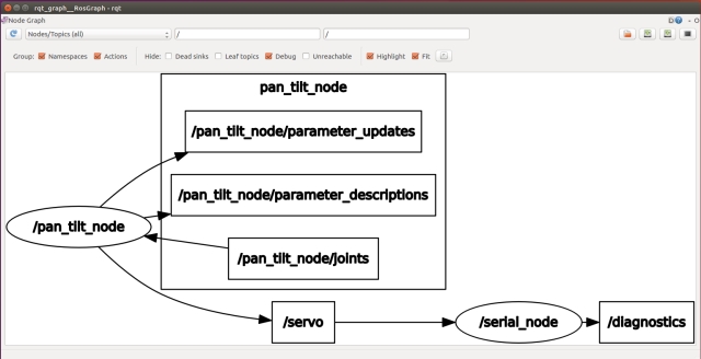
From the graph, you can see that the two nodes are running and are connected by the /servo topic. You can also see the topic /pan_tilt_node/joints.
We will now open a second terminal on the workstation and send a message to move the pan/tilt device using rostopic. In a new terminal, enter the following commands, don't forget to give the location of the master if running on a different device to that you launched the nodes on.
$ cd ~/test_ws
$ source devel/setup.bash
$ export ROS_MASTER_URI=http://ubiquityrobot:11311
$ rostopic pub -1 /pan_tilt_node/joints sensor_msgs/JointState
'{header: {seq: 0, stamp: {secs: 0, nsecs: 0}, frame_id: ""},
name: [ "head_pan","tilt_pan"], position: [0,0.349066], velocity: [], effort: []}'
The last command will result in rostopic publishing one instance of the /pan_tilt_node/joints topic of message type sensor_msgs/JointState with the pan position 0 radians and the tilt position 0.349066 radians. If all worked fine, the servos will move to the position given. Note that at this stage of the project, the servos move straight to the new position. In the next article, we will add a node that will move the head in a more controlled manner.
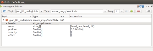
It can be a bit long-winded to type the rostopic command. Alternatively, you can use rqt GUI. In the terminal, type:
$ rosrun rqt_gui rqt_gui
This will launch a window where you can select the Message Publisher, choose the message to publish, and the message fields' contents.
Due to the mechanical fittings of the pan/tilt device, it may be off-center by a number of degrees. You can trim the servos with the following procedure:
Set the position of both servos to the mid positions.
$ rostopic pub -1 /pan_tilt_node/joints sensor_msgs/JointState
'{header: {seq: 0, stamp: {secs: 0, nsecs: 0}, frame_id: ""},
name: [ "head_pan","tilt_pan"], position: [0,0], velocity: [], effort: []}'
In a new terminal, start rqt_reconfigure with the following commands, don't forget to give the location of the master if running on a different device.
$ cd ~/test_ws
$ source devel/setup.bash
$ export ROS_MASTER_URI=http://ubiquityrobot:11311
$ rosrun rqt_reconfigure rqt_reconfigure
This will bring up a user interface like the one shown below. Trim parameters can be dynamically adjusted via the interface.
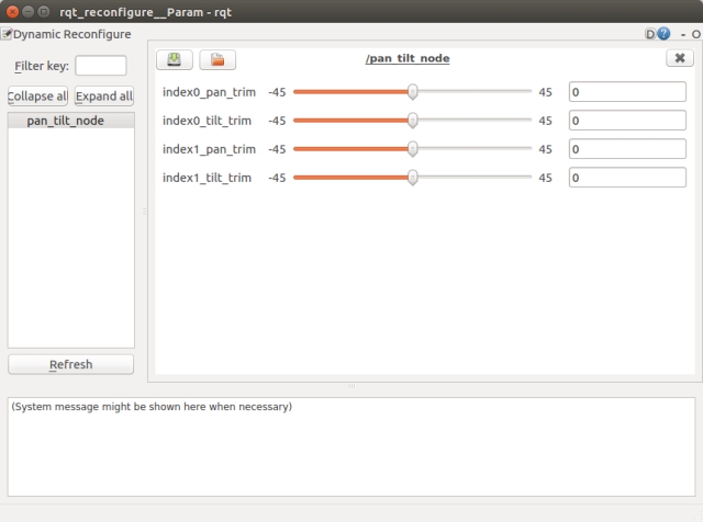
Once you are happy with the trim values, you can edit the pan_tilt.cfg to include the new trim values as the defaults. Then, the next time the nodes are started, these trim values will be used.
To terminate the nodes, simply hit Ctrl-c in the terminal.
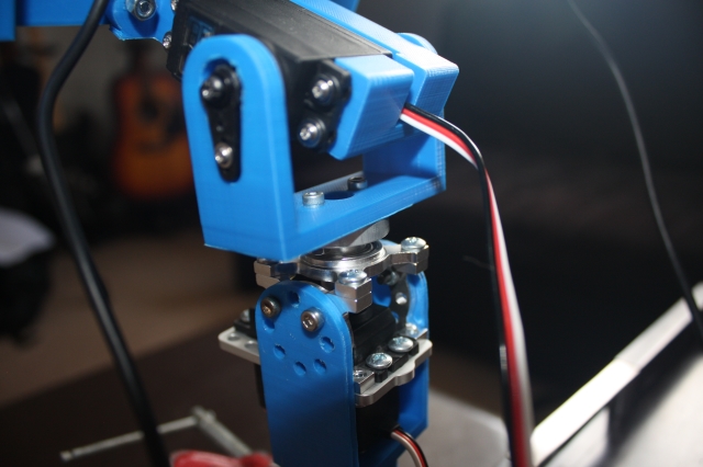
Pan-Tilt Mechanism
The EaseRobot's pan-tilt mechanism is comprised of two high-quality Futaba servos, specifically the S3003 and S3305 models. The S3305 servo, featuring metal gears, is employed in the pan position to ensure smooth and precise movement. Instead of purchasing a pre-made pan-tilt device, I opted to design and 3D print my own custom solution, with the STL files available for download. To mitigate the risk of the combined weight of the display and Raspberry Pi exerting excessive torque on the pan servo shaft, I incorporated a load-bearing servo block into the design. This innovative solution effectively enhances the mechanical load capacity of the servo, ensuring reliable operation. While this approach added to the overall cost of the robot, an alternative would be to mount the camera on a smaller pan-tilt device and fix the screen in place.
Key Takeaways
In this installment, we successfully integrated a ROS node from the broader ROS community into our EaseRobot system and developed our own custom ROS node. We have ROS running on the Raspberry Pi master board and have also leveraged the Arduino Nano to offload certain functionalities.
In the next installment, we will continue to work towards Design Goal 1 by integrating a Python-based face recognition library wrapped in a ROS node and developing a node to control the head movement.
Enhancing Our House Bot with Face Recognition and Head Control. In this installment of our ROS (Robot Operating System) House Bot series, we'll build upon the foundation established in Part 1 by incorporating face recognition and head control capabilities to achieve our Design Goal 1.
Introduction
The EaseRobot project is a hobbyist robotic endeavor aimed at designing and building an autonomous house-bot. This article is the second in the series, detailing the project's progress.
Background
In Part 1, we defined the requirements for our robot and broke down our mission into manageable Design Goals. Our mission, inspired by the article "Let's build a robot!", involves creating a robot that can take messages to family members. This capability will enable the robot to recognize individuals, navigate to their location, and deliver personalized messages.
The Design Goals for this mission are:
- To use the camera to search for faces, identify people, and display a message for recognized individuals
- To enable facial expressions and speech synthesis for message delivery
- To control locomotion using a remote keyboard and/or joystick
- To integrate a laser ranger finder or similar ranging sensor for navigation
- To achieve autonomous locomotion
- To assign and complete tasks with notification
In Part 1, we utilized ROS to add pan/tilt functionality to the head and camera. Here, we'll focus on adding face recognition and control nodes to complete Design Goal 1.
Mission 1, Design Goal 1 Continued
Accessing Images from the Raspberry Pi Camera
We'll leverage the ROS community's existing work to simplify our development process. The Raspberry Pi Ubuntu image includes a ROS package called raspicam_node, which we'll use to access the camera. If you're using a different OS image, you can install the node from the GitHub site.
To add the node to our system, we'll include a supplied ROS launch file in our launch file. We'll use an image resolution of 1280 x 960 pixels, so we'll add the following to our launch file:
<include file="$(find raspicam_node)/launch/camerav2_1280x960.launch" />
ROS uses its own image format to pass images between nodes. We'll need to convert ROS images to OpenCV images and back again using the cv_bridge package.
We'll write the face recognition node in Python, which will give us examples in both languages. We'll also utilize a Python face recognition library.
Detecting and Recognizing Faces
Before the system can recognize faces, we need to train it with the subjects we wish to recognize. We'll create two non-ROS Python scripts: data_set_generator.py and training.py. The first script will capture facial images of each subject using the camera, while the second script will use these images to train the system. The output of the second script is a yaml file containing the training data, which the ROS node will load during initialization.
Our ROS package for the node is called face_recognition and is available in the face_recognition folder. The subfolder scripts contains our two training scripts.
Each script utilizes face detection and face recognition built into OpenCV. If you're interested in understanding how this works, I recommend reading articles on the internet. I'll provide a high-level description of each script, starting with data_set_generator.py.
After the required imports, we load the classifier using the OpenCV library, declare a helper function to ensure that required folders exist, and create folders to hold captured images and training data
Next, we will guide you through the process of capturing face data for the EaseRobot project. This involves setting up the camera, creating a window to display the image, and prompting the user for input.
First, we set the camera resolution and initialize some variables, including the file name that stores our list of subjects. We then open the file and create a window to display the image read from the camera, allowing the subject to position themselves within the camera's field of view.
Next, the script prompts the user to enter the subject's unique ID, name, and whether it is a low-light condition. The unique IDs should start at 1 and increment by 1 for each new subject. It is recommended to run this script twice for each subject, once in bright light and once in low light conditions, to improve the recognition algorithm's success rate. Each run of the script will capture 100 images of the subject, with file names constructed from the subject ID and image number.
The script then adds the subject to the names file if they don't already exist.
with picamera.PiCamera() as camera:
  camera.resolution = (1280, 960)

  looping = True
  count = 0
  end = 99
  names_dict = {}
  name_file = '../trainer/names.yml'

  # Open the file of IDs and names to append the new one to
  if os.path.exists(name_file):
    with open(name_file, 'r') as stream:
      names_dict = yaml.load(stream)

  cv2.namedWindow('frame', cv2.WINDOW_NORMAL)

  face_id = input("What is this person's ID number? ")
  name = input("What is this person's name? ")
  low_light = input("Low light Y/N?" )

  if low_light == 'Y' or low_light == 'y':
    count = 100
    end = 199

  # If not already in the dictionary add details
  if not face_id in names_dict:
    names_dict[int(face_id)]=name

  with open(name_file, 'w') as outfile:
    yaml.dump(names_dict, outfile, default_flow_style=False)
The script then enters a loop to capture the images. Each pass of the loop captures an image from the camera, converts it to a numpy array, and attempts to detect a face in the image using OpenCV. If a face is detected, the image is cropped around the face, the number of image samples is incremented, and the cropped grey scale image is stored in the dataset folder. The original image from the camera, along with a superimposed frame around the face, is displayed to the user.
while(looping):
  # Create a memory stream so image doesn't need to be saved to a file
  stream = io.BytesIO()

  camera.capture(stream, format='jpeg')

  #Convert picture to numpy array
  buff = numpy.fromstring(stream.getvalue(), dtype=numpy.uint8)

  # Now create an OpenCV image
  image_frame = cv2.imdecode(buff, 1)

  # Convert frame to grayscale
  gray = cv2.cvtColor(image_frame, cv2.COLOR_BGR2GRAY)

  # Detect frames of different sizes, list of faces rectangles
  faces = face_detector.detectMultiScale(gray, 1.3, 5)

  # Although faces could contain more than one face we only expect one
  # person to be in the data set image otherwise it would confuse
  # the whole thing
  if (len(faces)!= 0):
    # Expecting one face only on the data set image
    (x, y, w, h) = faces[0]

    # Crop the image frame into rectangle
    cv2.rectangle(image_frame, (x,y), (x+w,y+h), (255,0,0), 4)

    # Increment sample face image
    count += 1

    # Save the captured image into the datasets folder
    cv2.imwrite("dataset/User." + str(face_id) + '.' + str(count) + ".jpg", gray[y:y+h,x:x+w])

    # Display the video frame, with bounded rectangle on the person's face
    cv2.imshow('frame', image_frame)

  # To stop taking video, press 'q' for at least 100ms
  if cv2.waitKey(100) & 0xFF == ord('q'):
    looping = False

  # If image taken reach 100, stop taking video
  elif count>end:
    looping = False
Finally, the script closes the window displaying the image and prints a message indicating that the process is complete.
# Close all started windows
cv2.destroyAllWindows()

print("Data prepared")
Once you have run the script for each subject, you can then run the training.py script to train the face recognition model.
The training.py script starts by importing the necessary libraries and defining the assure_path_exists function. It then creates instances of the OpenCV classes LBPHFaceRecognizer_create and CascadeClassifier using the same classifier file.
import cv2
import os
import numpy as np

def assure_path_exists(path):
  dir = os.path.dirname(path)
  if not os.path.exists(dir):
    os.makedirs(dir)

# Create Local Binary Patterns Histograms for face recognition
recognizer = cv2.face.LBPHFaceRecognizer_create()

# Using prebuilt frontal face training model, for face detection
detector = cv2.CascadeClassifier("../classifiers/haarcascade_frontalface_default.xml");
The get_images_and_labels function reads in each stored image, detects the face, and obtains the ID from the file name.
# Create method to get the images and label data
def get_images_and_labels(path):

  # Get all file paths
  image_paths = [os.path.join(path,f) for f in os.listdir(path)]

  # Initialize empty face samples
  face_samples=[]

  # Initialize empty IDs
  ids = []

  # Loop all the file paths
  for image_path in image_paths:

    # The stored image is grayscale so read in grayscale
    gray = cv2.imread(image_path, cv2.IMREAD_GRAYSCALE)

    # Get the image ID
    id = int(os.path.split(image_path)[-1].split(".")[1])

    # Get the face from the training images
    # Don't need any scaling as these images already full face
    faces = detector.detectMultiScale(gray);

    # During testing not always detected face on image, which
    # is odd as it should be just an image that was saved
    if (len(faces) == 0):
      print "No face on " + image_path

    else:
      # We know each image is only of one face
      (x, y, w, h) = faces[0]

      # Add the image to face samples
      face_samples.append(gray[y:y+h,x:x+w])

      # Add the ID to IDs
      ids.append(id)

  # Pass the face array and IDs array
  return face_samples,ids
Once all the faces and IDs are obtained, they are passed to the OpenCV face recognizer, and the data from the recognizer is saved to disk. The face recognition library that will be used by our node will later load this data to train the recognizer.
# Get the faces and IDs
faces,ids = get_images_and_labels('dataset')

# Train the model using the faces and IDs
recognizer.train(faces, np.array(ids))

# Save the model into trainer.yml
assure_path_exists('../trainer/')
recognizer.save('../trainer/trainer.yml')

print("Done")
The code for the ROS node itself is in the subfolder src in the file face_recognition_node.py. The code makes use of a library file, face_recognition_lib.py, which contains the class FaceRecognition. This file is in the subfolder src/face_recognition_lib.
Before describing the code for the node, we'll discuss the FaceRecognition class. After the required imports and the declaration of the class, it defines a number of functions.
The class constructor creates the OpenCV face recognizer and then reads the training file created by the training script. It then opens the file containing the list of names and the IDs, and creates the classifier. It finally stores a confidence value passed to it. This value will be used to determine if the suggested ID for the face is accepted.
def __init__(self, path, confidence):
  # Create Local Binary Patterns Histograms for face recognition
  self.__face_recognizer = cv2.face.LBPHFaceRecognizer_create()

  # Load the trained model
  self.__face_recognizer.read(path + '/trainer/trainer.yml')

  # Load the names file
  with open(path + '/trainer/names.yml', 'r') as stream:
    self.__names_dict = yaml.load(stream)

  # Detect object in image using Haarcascade Frontal Face
  self.__face_detector = cv2.CascadeClassifier
       (path + '/classifiers/haarcascade_frontalface_default.xml')

  # Confidence level,
  # the confidence of the system in recognising a face must be greater than
  # this level to be accepted by the system as a recognised face.
  self.__confidence_level = confidence
Two functions are declared which will be used to modify the captured image if a face is detected. The first will draw a rectangle on the image, and the second will draw the supplied text on the image.
# Function to draw rectangle on image according to given (x, y) coordinates
# and the given width and height
def draw_rectangle(self, img, rect, bgr):
  (x, y, w, h) = rect
  cv2.rectangle(img, (x, y), (x+w, y+h), bgr, 4)

# Function to draw text on give image starting at the passed (x, y) coordinates.
def draw_text(self, img, text, x, y, bgr):
  cv2.putText(img, text, (x, y), cv2.FONT_HERSHEY_PLAIN, 3.0, bgr, 4)
The detect_faces function is responsible for detecting faces in a supplied image. It converts the image to grayscale, allowing OpenCV to detect faces. If faces are detected, the function returns the face data and their locations in the image. This function is designed to handle multiple faces in a single image.
def detect_faces(self, img):
    face_data = []
    gray = cv2.cvtColor(img, cv2.COLOR_BGR2GRAY)
    faces_detected = self.__face_detector.detectMultiScale(gray, 1.3, 5)
    if len(faces_detected) == 0:
        return None, None
    for face in faces_detected:
        (x, y, w, h) = face
        face_data.append(gray[y:y+w, x:x+h])
    return face_data, faces_detected
The scan_for_faces function is the primary entry point for face detection and recognition. It calls the detect_faces function and, if faces are detected, loops through each face, using OpenCV's face predictor to recognize the individual. The confidence level of the prediction is converted to a percentage and, if it exceeds a predefined threshold, the face is highlighted in green; otherwise, it is highlighted in red. The function returns a dictionary containing the IDs and names of recognized individuals.
def scan_for_faces(self, img):
    faces, rects = self.detect_faces(img)
    detected_dict = {}
    if faces is not None:
        for index in range(len(faces)):
            label, confidence = self.__face_recognizer.predict(faces[index])
            our_confidence = round(100 - confidence, 2)
            name_text = self.__names_dict[label]
            name_text_confidence = name_text + " {0:.2f}%".format(our_confidence)
            if our_confidence > self.__confidence_level:
                colour = (0, 255, 0)
            else:
                colour = (0, 0, 255)
            self.draw_rectangle(img, rects[index], colour)
            self.draw_text(img, name_text_confidence, rects[index,0], rects[index,1]-5, colour)
            if our_confidence > self.__confidence_level:
                detected_dict[label] = name_text
    return detected_dict
The ROS node initializes the FaceRecognitionNode class, which creates an instance of CVBridge to convert ROS images to OpenCV images. It publishes the topic face_recognition_node/image/compressed and subscribes to the topic raspicam_node/image/compressed. The node reads the confidence threshold from the parameter server and sets it to 20% by default.
def main(args):
    rospy.init_node('face_recognition_node', anonymous=False)
    frn = FaceRecognitionNode()
    rospy.loginfo("Face recognition node started")
    try:
        rospy.spin()
    except KeyboardInterrupt:
        print("Shutting down")

if __name__ == '__main__':
    main(sys.argv)
The FaceRecognitionNode class is responsible for face detection and recognition, and its constructor initializes the necessary components for this functionality.
class FaceRecognitionNode:
    def __init__(self):
        self.__bridge = CvBridge()
        self.__image_pub = rospy.Publisher('face_recognition_node/image/compressed',
                            CompressedImage, queue_size=1)
        self.__image_sub = rospy.Subscriber('raspicam_node/image/compressed',
                           CompressedImage, self.callback)

        confidence_level = rospy.get_param('/face_rec_python/confidence_level', 20)
        rospy.loginfo("FaceRecognitionNode: Confidence level %s", str(confidence_level))

        # Create the face_recognition_lib class instance
        self.__frc = face_recognition_lib.FaceRecognition(
            (roslib.packages.get_pkg_dir('face_recognition', required=True), confidence_level)
        )

        # Create the Action server
        self.__as = actionlib.SimpleActionServer(
            'face_recognition', scan_for_facesAction, self.do_action, False
        )
        self.__as.start()
The do_action function is called by the action server when a request to conduct the action is received. It converts the last received image from a ROS image to an OpenCV image, scans the image for known faces using the scan_for_faces function, and publishes the adjusted image on the face_recognition_node/image/compressed topic.
def do_action(self, goal):
    # Scan the current image for faces recognised
    image = self.__bridge.compressed_imgmsg_to_cv2(self.__current_image)
    detected_dict = self.__frc.scan_for_faces(image)

    try:
        self.__image_pub.publish(self.__bridge.cv2_to_compressed_imgmsg(image))
    except CvBridgeError as e:
        print(e)

    # Now post a message with the list of IDs and names
    ids = []
    names = []
    for k, v in detected_dict.items():
        ids.append(k)
        names.append(v)
    # Set result for the action
    result = scan_for_facesResult()
    result.ids_detected = ids
    result.names_detected = names
    self.__as.set_succeeded(result)
The callback function is called each time a message is received on the raspicam/image/compressed topic. It simply stores the current image for facial recognition.
def callback(self, data):
    # Each time we receive an image we store it ready in case then asked to scan it
    self.__current_image = data
The node package includes a config.yaml file for setting the confidence level without recompiling the code. Additionally, a test.launch file is provided for testing the node, which launches the camera node and the face recognition node.
Face Recognition Action
The face recognition package utilizes a user-defined action message to initiate the operation and return the results of identifying known faces. The face_recognition_msgs package contains the scan_for_faces.action file, which is located in the action subfolder.
The action specification consists of three main sections: goal, result, and feedback. It resembles a message definition file, with each section separated by three dashes (---).
uint16[] ids_detected
string[] names_detected
The goal section, above the first three dashes, does not require any parameters. The receipt of the goal will trigger the action.
The result section, below the first three dashes, contains an array of IDs and an array of names for any recognized faces.
The feedback section, below the second three dashes, does not provide any feedback in this case.
Controlling the Head
We have now developed a node to perform facial recognition on an image from the camera and, from part 1 of this article, we have the pan/tilt functionality to move the servos connected to the head. We will create a new node that accepts a target position for the head, but moves the head to that target in incremental steps to prevent the robot from rocking when the head moves from one extreme to the other. The node will also accept both absolute positions and relative distances to move from the current position.
Our ROS package for this node is called head_control and is located in the head_control folder. The package contains all the usual ROS files and folders.
The action folder contains the point_head.action file, which defines an action that passes a goal containing the target position and feedback on the current position of the head.
bool absolute
float64 pan
float64 tilt
float64 current_pan
float64 current_tilt
The goal contains pan and tilt values in radians, as well as a boolean flag absolute. If absolute is true, the pan and tilt values represent the absolute target position. If absolute is false, the values represent the relative distance to move the head.
The feedback values provide the current position of the head as it moves towards the target position.
The config folder contains a config.yaml file that can be used to override default configuration values. You can configure:
The default position of the head The maximum value the pan and tilt device should move per request, to prevent the servo from moving a large angle in one step and causing the head to shudder
head:
position:
pan: 0.0
tilt: 0.0
max_step:
pan: 0.0872665
tilt: 0.0872665
The include/head_control and src folders contain the C++ code for the package. We have one C++ class, HeadControlNode, and a main routine within the head_control_node.cpp file.
The main routine informs ROS of our node, creates an instance of the class for the node, and passes it the node handle and node name. For the first time in this project, we will not hand total control of the node to ROS. Instead, we will retain control to move the servos in small incremental steps to a target position.
Before entering the loop, we create an instance of ros::Rate and pass it the desired timing, in this case, 10Hz. Inside the loop, we call r.sleep, which attempts to maintain the loop at 10Hz by accounting for the time used to complete the work in the loop.
Our loop will continue until the call to ros::ok returns false, indicating that the node has finished shutting down.
In the loop, we will call moveServo, which is described later in the article.
int main(int argc, char **argv)
{
ros::init(argc, argv, "head_control_node");
ros::NodeHandle n;
std::string node_name = ros::this_node::getName();
HeadControlNode head_control(n, node_name);
ROS_INFO("%s started", node_name.c_str());

// We need control of the node to step the servos to the target position in small steps
ros::Rate r(10); // 10Hz

while(ros::ok())
{
    // Check if the servos need moving
    head_control.moveServo();

    ros::spinOnce();
    r.sleep();
}
return 0;

}
The rest of the file contains the HeadControlNode class.
The constructor for HeadControlNode registers the callback function pointHeadCallback with the action server. This callback will be called when the action server receives the action goal, initiating the action.
The constructor for the HeadControlNode class initializes the action server and sets up the node's configuration. It starts the server with the as_.start() call.
The constructor advertises that it will publish the pan_tilt_node/joints topic, which will be used to pass the required pan/tilt position to the pan/tilt node.
// Constructor
HeadControlNode::HeadControlNode(ros::NodeHandle n, std::string name) : as_(n, name, false)
{
    nh_ = n;

    as_.registerGoalCallback(boost::bind(&HeadControlNode::pointHeadCallback, this));
    as_.start();

    // Topic to move head
    move_head_pub_ = nh_.advertise<sensor_msgs::JointState>("pan_tilt_node/joints", 10, true);

    // Obtain any configuration values from the parameter server.
    // If they don't exist use the defaults

    // Joint names
    nh_.param<std::string>("/servo/index0/pan/joint_name", pan_joint_name_, "reserved_pan0");
    nh_.param<std::string>("/servo/index0/tilt/joint_name", tilt_joint_name_, "reserved_tilt0");

    // Maximum angle we can move in one go
    nh_.param("/head/max_step/pan", pan_step_, 0.174533);
    nh_.param("/head/max_step/tilt", tilt_step_, 0.174533);

    double pan;      // Pan default position to return to
    double tilt;     // Tilt default position to return to
    nh_.param("/head/position/pan", pan, 0.0);
    nh_.param("/head/position/tilt", tilt, 0.0);
    default_position_.pan = pan;
    default_position_.tilt = tilt;

    // Set up the message we will publish
    msg_.name.push_back(pan_joint_name_);
    msg_.name.push_back(tilt_joint_name_);
    msg_.position.push_back(0.0);
    msg_.position.push_back(0.0);

    // We will often return to this position when a task is completed
    current_pan_tilt_ = default_position_;
    // We don't know where the servo starts from so just jump to the required position
    // Publish a start position to get the head in a known position.
    publishJointState(current_pan_tilt_);

    move_head_ = false;
    movement_complete_ = false;
    target_pan_tilt_ = current_pan_tilt_;
}
It then sets some configuration defaults and reads any overrides from the parameter server should they be available.
Next, it sets the names of the joints in the joint state message, which will not change.
Finally, it publishes a message to move the head to a known starting point. This is necessary because we don't know the starting position of the head after power-up, so we can't move to the target position in small steps.
// This callback is for the point head action
void HeadControlNode::pointHeadCallback()
{
    head_control::point_headGoal::ConstPtr goal;

    goal = as_.acceptNewGoal();

    // Set the target position to the request position
    if (goal->absolute == true)
    {
        target_pan_tilt_.pan = goal->pan;
        target_pan_tilt_.tilt = goal->tilt;
    }
    else
    {
        target_pan_tilt_.pan += goal->pan;
        target_pan_tilt_.tilt += goal->tilt;
    }

    // Indicate that the servos should be moved
    move_head_ = true;

    movement_complete_ = false;
}
The pointHeadCallback function is called by ROS when the action server receives a goal message. The goal data is either the absolute or relative target position, depending on the state of the absolute flag.
The function calls the action server to inform it that the goal has been accepted, stores the new target position, and sets the move_head flag to true, indicating that the head needs to be moved.
// Function to move the servos if required by a step amount.
// This is to stop the head shuddering if the servo
// is moved to the target position in one movement.
void HeadControlNode::moveServo()
{
    if(move_head_ == true)
    {
        if(as_.isPreemptRequested() || !ros::ok())
        {
            as_.setPreempted();
            movement_complete_ = false;
            move_head_ = false;
        }
        else if(movement_complete_ == true)
        {
            // We have reached the target but give time to settle
            loop_count_down_--;

            if(loop_count_down_ <= 0)
            {
                movement_complete_ = false;
                move_head_ = false;
                head_control::point_headResult result;
                as_.setSucceeded(result);
            }
        }
        else
        {
            if((target_pan_tilt_.pan == current_pan_tilt_.pan) &&
               (target_pan_tilt_.tilt == current_pan_tilt_.tilt))
            {
                // Last time around we must have requested the final move
                movement_complete_ = true;
                loop_count_down_ = 8;
            }
            else
            {
                // Still moving, calculate pan movement
                if(std::abs(target_pan_tilt_.pan - current_pan_tilt_.pan) > pan_step_)
                {
                    // Distance to target to great to move in one go
                    if(target_pan_tilt_.pan > current_pan_tilt_.pan)
                    {
                        // Add the step to current
                        current_pan_tilt_.pan += pan_step_;
                    }
                    else
                    {
                        // Subtract step from current
                        current_pan_tilt_.pan -= pan_step_;
                     }
                }
                else
                {
                    // Can move to the target position in one go
                    // (or pan is in fact already there but tilt is not)
                    current_pan_tilt_.pan = target_pan_tilt_.pan;
                }

                // Calculate tilt movement
                if(std::abs(target_pan_tilt_.tilt - current_pan_tilt_.tilt) > tilt_step_)
                {
                    // Distance to target to great to move in one go
                    if(target_pan_tilt_.tilt > current_pan_tilt_.tilt)
                    {
                        // Add the step to current
                        current_pan_tilt_.tilt += tilt_step_;
                    }
                    else
                    {
                        // Subtract step from current
                        current_pan_tilt_.tilt -= tilt_step_;
                     }
                }
                else
                {
                    // Can move to the target position in one go
                    // (or tilt is in fact already there but pan is not)
                    current_pan_tilt_.tilt = target_pan_tilt_.tilt;
                }

                // Publish the movement
                publishJointState(current_pan_tilt_);

                // Publish feedback
                head_control::point_headFeedback feedback;
                feedback.current_pan = current_pan_tilt_.pan;
                feedback.current_tilt = current_pan_tilt_.tilt;
                as_.publishFeedback(feedback);
            }
        }
    }
}
The moveServo function is called by the main loop in our code. It checks to see if a request to move the head was made and, if so, enters an 'if', 'else if', 'else' construct.
The 'if' part of this construct checks to see if the action has been pre-empted. If so, it accepts the pre-emption and tidies up.
The 'else if' part checks to see if the head movement is complete. If so, a counter is decremented. This counter is used to include time for the head to stop moving and blurring any camera images after the servos reach the target position. When the counter reaches zero, the fact that the action is complete is reported to the action server.
The 'else' part is responsible for calculating the next step movement of the servos towards the target position, publishing the joint state message with the next required servo position using the helper function publishJointState, and reporting the feedback to the action server.
// This function creates and publishes a joint state message
void HeadControlNode::publishJointState(struct position pan_tilt)
{
    msg_.position[0] = pan_tilt.pan;
    msg_.position[1] = pan_tilt.tilt;
    msg_.header.stamp = ros::Time::now();

    move_head_pub_.publish(msg_);
}
The publishJointState function is a helper function that updates the position values in the joint state message and then publishes the message.
This file, test.launch, will launch all the nodes developed to move the head.
<?xml version="1.0" ?>
<launch>
  <rosparam command="load" file="$(find pan_tilt)/config/config.yaml" />
  <rosparam command="load" file="$(find head_control)/config/config.yaml" />

  <node pkg="pan_tilt" type="pan_tilt_node" name="pan_tilt_node" output="screen" />
  <node pkg="rosserial_python" type="serial_node.py"
   name="serial_node" output="screen" args="/dev/ttyUSB0"/>
  <node pkg="head_control" type="head_control_node" name="head_control_node" output="screen"/>
</launch>
Action Client
In our previous sections, we explored the concept of action servers in both our nodes. Now, we will delve into the world of action clients, which enable communication with the server. Later in this article, we will introduce a ROS package that allows us to create state machines and sub-state machines to control our robot missions. Using this package, we can assign an individual state to be the action client, and all communication is handled seamlessly behind the scenes.
To test the system we have developed so far and to demonstrate how to write an action client, we will create two test nodes. Each node will include an action client.
Our first node is a simple Python node designed to test the face recognition node. The ROS package for this node is called ease_robot_recognition_test and is available in the ease_robot_recognition_test folder. The package contains all the usual ROS files and folders.
All the code is contained in the ease_robot_recognition_test_node.py file in the src folder.
The code initializes our node and creates an action client. Note that the name passed to the SimpleActionClient, in our case 'face_recognition', must match the name given to the action server.
We then call wait_for_server, and the code will wait here until it is able to make contact with the server. We then create a goal, which in this case contains no data, and send the goal to the server.
In our simple example, we then wait until the result is returned, and the node finishes by printing the ID and names of any faces recognized and returned in the result.
#!/usr/bin/env python

import rospy
import actionlib
from face_recognition_msgs.msg import scan_for_facesAction,
     scan_for_facesGoal, scan_for_facesResult

rospy.init_node('face_recognition_client')
client = actionlib.SimpleActionClient('face_recognition', scan_for_facesAction)
client.wait_for_server()
goal = scan_for_facesGoal()
client.send_goal(goal)
client.wait_for_result()
result = client.get_result()
print(result.ids_detected)
print(result.names_detected)
Our next package is designed to test the head_control node. We will write a slightly more complicated node, this time written in C++.
Our ROS package is called ease_robot_head_test and is available in the ease_robot_head_test folder. The package contains all the usual ROS files and folders.
The include/ease_robot_head_test and src folders contain the C++ code for the package. For this package, we have one C++ class, EaseRobotHeadTestNode, and a main routine contained within the ease_robot_head_test_node.cpp file.
The main routine informs ROS of our node, creates an instance of the class for the node, and passes it the node handle, logs that the node has started, and hands control to ROS with the call to ros::spin.
int main(int argc, char **argv)
{
    ros::init(argc, argv, "ease_robot_head_test");
    ros::NodeHandle n;
    EaseRobotHeadTestNode ease_robot_head_test_node(n);
    std::string node_name = ros::this_node::getName();
    ROS_INFO("%s started", node_name.c_str());
    ros::spin();
    return 0;
}
The constructor creates an instance of our action client, ac_, and passes it the name of the action server, which in our case is head_control_node. This must match the name we gave to our action server when we created it in the HeadControlNode constructor.
We then read the config parameters to limit the movement of the servos.
We are going to use a keyboard node, available from https://github.com/lrse/ros-keyboard, to interact with the system. In the constructor, we subscribe to the topic keyboard/keydown and call the function keyboardCallBack when a message is received on that topic.
The call ac_.waitForServer will wait in the constructor until our action server is running.
// Constructor
EaseRobotHeadTestNode::EaseRobotHeadTestNode(ros::NodeHandle n) : ac_("head_control_node", true)
{
    nh_ = n;

    // Subscribe to receive keyboard input
    key_sub_ = nh_.subscribe("keyboard/keydown", 100,
               &EaseRobotHeadTestNode::keyboardCallBack, this);

    nh_.param("/servo/index0/pan/max", max_pan_radians_, M_PI/2.0);
    nh_.param("/servo/index0/pan/min", min_pan_radians_, -(M_PI/2.0));
    nh_.param("/servo/index0/tilt/max", max_tilt_radians_, M_PI/2.0);
    nh_.param("/servo/index0/tilt/min", min_tilt_radians_, -(M_PI/2.0));

    ROS_INFO("EaseRobotHeadTestNode: Waiting for action server to start");

    // wait for the action server to start
    ac_.waitForServer(); //will wait for infinite time

    moving_ = false;

    ROS_INFO("EaseRobotHeadTestNode: Action server started");
}
The function keyboardCallBack checks the received message and runs a test dependent on the key pressed.
It creates an instance of our action goal, sets the goal parameters, and passes it to the action server with a call to ac_.sendGoal. With the call, we pass three callback functions:
doneCBwhich is called when the action is completedactiveCBwhich is called when the action goes active andfeedbackCBwhich is called when the feedback on the progress of the action is received
The action can be pre-empted, so if the 'c' key is pressed and moving the head is in progress, we will cancel the action with a call to ac_.cancelGoal.
void EaseRobotHeadTestNode::keyboardCallBack(const keyboard::Key::ConstPtr& msg)
{
    head_control::point_headGoal goal;

    // Check for key 1 with no modifiers apart from num lock is allowed
    if((msg->code == keyboard::Key::KEY_1) &&
      ((msg->modifiers & ~keyboard::Key::MODIFIER_NUM) == 0))
    {
        // Key 1, Test 1 move to max pan and tilt
        goal.absolute = true;
        goal.pan      = max_pan_radians_;
        goal.tilt     = max_tilt_radians_;
        // Need boost::bind to pass in the 'this' pointer
        ac_.sendGoal(goal,
            boost::bind(&EaseRobotHeadTestNode::doneCB, this, _1, _2),
            boost::bind(&EaseRobotHeadTestNode::activeCB, this),
            boost::bind(&EaseRobotHeadTestNode::feedbackCB, this, _1));
    }
    if((msg->code == keyboard::Key::KEY_2) &&
      ((msg->modifiers & ~keyboard::Key::MODIFIER_NUM) == 0))
    {
        // Key 2, test 2 move to min pan and tilt
        goal.absolute = true;
        goal.pan      = min_pan_radians_;
        goal.tilt     = min_tilt_radians_;
        // Need boost::bind to pass in the 'this' pointer
        ac_.sendGoal(goal,
            boost::bind(&EaseRobotHeadTestNode::doneCB, this, _1, _2),
            boost::bind(&EaseRobotHeadTestNode::activeCB, this),
            boost::bind(&EaseRobotHeadTestNode::feedbackCB, this, _1));
    }
    if((msg->code == keyboard::Key::KEY_3) &&
      ((msg->modifiers & ~keyboard::Key::MODIFIER_NUM) == 0))
    {
        // Key 3, test 3 move to pan 0, tilt 0
        goal.absolute = true;
        goal.pan      = 0.0;
        goal.tilt     = 0.0;
        // Need boost::bind to pass in the 'this' pointer
        ac_.sendGoal(goal,
            boost::bind(&EaseRobotHeadTestNode::doneCB, this, _1, _2),
            boost::bind(&EaseRobotHeadTestNode::activeCB, this),
            boost::bind(&EaseRobotHeadTestNode::feedbackCB, this, _1));
    }
    if((msg->code == keyboard::Key::KEY_4) &&
      ((msg->modifiers & ~keyboard::Key::MODIFIER_NUM) == 0))
    {
        // Key 4, test 4 move to pan 0, tilt -45 degress
        goal.absolute = true;
        goal.pan      = 0.0;
        goal.tilt     = -0.785398;
        // Need boost::bind to pass in the 'this' pointer
        ac_.sendGoal(goal,
            boost::bind(&EaseRobotHeadTestNode::doneCB, this, _1, _2),
            boost::bind(&EaseRobotHeadTestNode::activeCB, this),
            boost::bind(&EaseRobotHeadTestNode::feedbackCB, this, _1));
    }
    if((msg->code == keyboard::Key::KEY_5) &&
      ((msg->modifiers & ~keyboard::Key::MODIFIER_NUM) == 0))
    {
        // Key 5, test 5 move tilt up by 10 degrees
        goal.absolute = false;
        goal.pan      = 0;
        goal.tilt     = -0.174533;
        // Need boost::bind to pass in the 'this' pointer
        ac_.sendGoal(goal,
            boost::bind(&EaseRobotHeadTestNode::doneCB, this, _1, _2),
            boost::bind(&EaseRobotHeadTestNode::activeCB, this),
            boost::bind(&EaseRobotHeadTestNode::feedbackCB, this, _1));
    }
    if((msg->code == keyboard::Key::KEY_6) &&
      ((msg->modifiers & ~keyboard::Key::MODIFIER_NUM) == 0))
    {
        // Key 6, test 6 move pan by 20 anti-clockwise
        goal.absolute = false;
        goal.pan      = 0.349066;
        goal.tilt     = 0;
        // Need boost::bind to pass in the 'this' pointer
        ac_.sendGoal(goal,
            boost::bind(&EaseRobotHeadTestNode::doneCB, this, _1, _2),
            boost::bind(&EaseRobotHeadTestNode::activeCB, this),
            boost::bind(&EaseRobotHeadTestNode::feedbackCB, this, _1));
    }
    if((msg->code == keyboard::Key::KEY_7) &&
      ((msg->modifiers & ~keyboard::Key::MODIFIER_NUM) == 0))
    {
        // Key 7, test 7 move pan by 20 clockwise and tilt by 10 down
        goal.absolute = false;
        goal.pan      = -0.349066;
        goal.tilt     = 0.174533;
        // Need boost::bind to pass in the 'this' pointer
        ac_.sendGoal(goal,
            boost::bind(&EaseRobotHeadTestNode::doneCB, this, _1, _2),
            boost::bind(&EaseRobotHeadTestNode::activeCB, this),
            boost::bind(&EaseRobotHeadTestNode::feedbackCB, this, _1));
    }
    else if((msg->code == keyboard::Key::KEY_c) &&
           ((msg->modifiers & ~EaseRobotHeadTestNode::SHIFT_CAPS_NUM_LOCK_) == 0))
    {
        // Key 'c' or 'C', cancel action
        if(moving_ == true)
        {
            ac_.cancelGoal();
        }
    }
    else
    {
        ;
    }
}
The callback function activeCB is called when the action goes active, at which point we log the fact and set a member variable indicating that movement is taking place.
// Called once when the goal becomes active
void EaseRobotHeadTestNode::activeCB()
{
    ROS_INFO("EaseRobotHeadTestNode: Goal just went active");

    moving_ = true;
}
The callback function feedbackCB is called when feedback on the progress of the action is received. If you recall, our feedback includes the current position of the servos on their way to the target position.
// Called every time feedback is received for the goal
void EaseRobotHeadTestNode::feedbackCB(const head_control::point_headFeedbackConstPtr& feedback)
{
    ROS_INFO("Feedback pan=%f, tilt=%f", feedback->current_pan, feedback->current_tilt);
}
The callback function doneCB is called when the action is completed. In this case, the result data is empty.
// Called once when the goal completes
void EaseRobotHeadTestNode::doneCB(const actionlib::SimpleClientGoalState& state,
                        const head_control::point_headResultConstPtr& result)
{
    ROS_INFO("EaseRobotHeadTestNode: Finished in state [%s]", state.toString().c_str());
    moving_ = false;
}
Using the Code
In this article, we will test the two nodes individually. In Part 4, we will put the two together so that the robot can scan a room within its head movement range looking for faces it recognises.
As previously when testing the code, I'm going to run the system code on the Raspberry Pi and the test code on a separate Linux workstation. The Raspberry Pi will also be connected to the Arduino nano which in turn is connected to the servos and running the sketch from part one of the article.
Note that to distinguish between the Pi and the workstation in the instructions below, the code is in a folder (workspace) called "easerobot_ws" on the Pi and "test_ws" on the workstation. Building the ROS Packages on the Pi
If not already done, create a catkin workspace on the Raspberry Pi and initialise it with the following commands:
$ mkdir -p ~/easerobot_ws/src
$ cd ~/easerobot_ws/
$ catkin_make
Copy the packages face_recognition, face_recognition_msgs, head_control, pan_tilt, and servo_msgs into the ~/easerobot_ws/src folder and then build the code. As a little tip, I don't copy the code into the src folder but create a symbolic link in the src folder to the code location. That way, I can have a number of workspaces using the same code files.
$ cd ~/easerobot_ws/
$ catkin_make
Check that the build completes without any errors.
Building the ROS Test Packages on the Workstation
You can build and run the test packages on the Raspberry Pi but I'm going to use a Linux workstation which is on the same network as the Pi.
Create a workspace with the following commands:
$ mkdir -p ~/test_ws/src
$ cd ~/test_ws/
$ catkin_make
Copy the packages face_recognition, face_recognition_msgs, head_control, pan_tilt, servo_msgs, easerobot_recognition_test, easerobot_head_test, and ros-keyboard (from https://github.com/lrse/ros-keyboard) into the ~/test_ws/src folder and then build the code with the following commands:
$ cd ~/test_ws/
$ catkin_make
Check that the build completes without any errors.
Tip
When running ROS code and tools on a workstation and the Raspberry Pi, there can be a lot of repeat typing of commands at a number of terminals. In the next section, I have included the full commands to type but here are a few tips that can save you all that typing.
On the Raspberry Pi to save typing "source devel/setup.bash" I have added it to the .bashrc file for the Raspberry Pi.
$ cd ~/
$ nano .bashrc
Then add "source /home/ubuntu/easerobot_ws/devel/setup.bash" to the end of the file, save and exit.
When running test code and tools on the workstation, it also needs to know where the ROS master is so I have added the following to the .bashrc file for the workstation.
alias easerobot='source ~/test_ws/devel/setup.bash; \
export ROS_MASTER_URI=http://ubiquityrobot:11311'
Then by just typing "easerobot" at a terminal, the two commands are run and a lot of typing is saved.
Running the Code
First, we will test the face recognition node. Use the launch file to start the nodes with the following commands on the Raspberry Pi:
$ cd ~/easerobot_ws/
$ source devel/setup.bash
$ roslaunch face_recognition test.launch
With the nodes running on the Raspberry Pi, I'm going to use a Linux workstation on the same network to run some tests. Note: As we will use our user defined topics, the code also needs to be built on this workstation. You can, if you wish, run the tests on the same Raspberry Pi running the system nodes.
At the workstation, run the following to check that the nodes are running and connected to the correct topics. You can see the name of master in the output from running roslaunch. As I'm using the Ubiquity ROS Ubuntu image and have not changed the name, my master is ubiquityrobot.
$ export ROS_MASTER_URI=http://ubiquityrobot:11311
$ rqt_graph
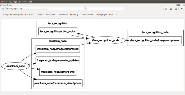
If any topics have been misspelt in one part of the code, then it will be obvious from the graph as the nodes will not be joined by the topics.
In another terminal, enter the following in order to be able to view the images.
$ export ROS_MASTER_URI=http://ubiquityrobot:11311
$ rqt_image_view
In the Image View GUI, you can select the topic /raspicam/image/compressed to view the current camera image. For the test, I'm going to select the topic /face_recognition_node/image/compressed, the image will currently be blank but when we request a face recognition operation, we will be able to view the result.
In a new terminal, run the test node to conduct the face recognition process on an image from the camera.
$ cd ~/test_ws
$ export ROS_MASTER_URI=http://ubiquityrobot:11311
$ source devel/setup.bash
$ rosrun easerobot_recognition_test easerobot_recognition_test_node.py
You can rerun the process by just entering the last line again in the same terminal. The result of each run will be shown in the rqt_image_view window and output in the terminal.
When I ran the test without anyone in view of the camera, the image viewer displayed an image of the room and the terminal reported empty results with:
() []
When run with myself in view of the camera, the terminal and the image viewer displayed the following:
(1,) ['Phil']
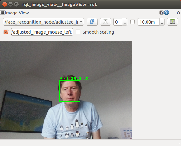
When testing with two people in the image, it's trained for both these subjects, I got the following results:
(1, 2,) [Phil, Dave]
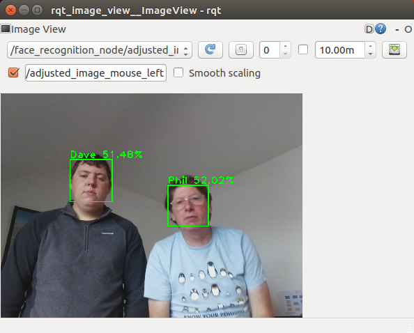
You can close down each terminal on the workstation and the Pi by entering Ctrl-C in the terminal.
Next we will test the head control node. With the Arduino connected to a USB port of the Pi, use the launch file to start the nodes with the following commands:
You can rerun the process by just entering the last line again in the same terminal. The result of each run will be shown in the rqt_image_view window and output in the terminal.
$ cd ~/easerobot_ws/
$ source devel/setup.bash
$ roslaunch head_control test.launch
When the code starts, the head will move to the default position.
Next, I'm going to use rqt_graph and our test code to test the system. On the workstation, run the following commands to start the keyboard node:
$ cd ~/test_ws
$ source devel/setup.bash
$ export ROS_MASTER_URI=http://ubiquityrobot:11311
$ rosrun keyboard keyboard
On the workstation in a second terminal, run the following commands to start our test node:
$ cd ~/test_ws
$ source devel/setup.bash
$ export ROS_MASTER_URI=http://ubiquityrobot:11311
$ rosrun easerobot_head_test easerobot_head_test_node
In a third terminal, run the following commands to start rqt_graph:
$ cd ~/test_ws
$ export ROS_MASTER_URI=http://ubiquityrobot:11311
$ rqt_graph
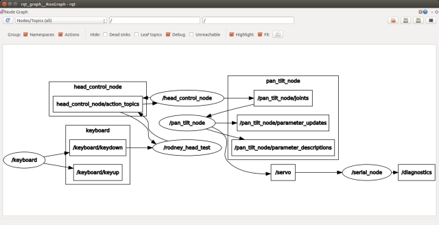
From the graph, you should see the nodes under test and the test code running. You should also see the nodes linked by the topics. Any broken links is an indication of misspelt topics in the code.
The workstation should also be running a small window whose title is "ROS keyboard input". Make sure this window has the focus and then press a key for the following tests. During a scan head movement, you can press the 'c' key to cancel the action.
- Key '1' - The head will move to the maximum pan and tilt position (left and down)
- Key '2' - The head will move to the minimum pan and tilt position (right and up)
- Key '3' - The head will move back to zero pan and tilt position
- Key '4' - The head will tilt to up to the 45 degrees position
- Key '5' - The head will move up from the current position by 5 degrees
- Key '6' - The head will move anti-clockwise (left) from the current position by 20 degrees
- Key '7' - The head will move clockwise (right) from the current position by 20 degrees and down by 10 degrees
Summary
In this installment, we've successfully integrated face recognition and head control capabilities into our code, thereby fulfilling Design Goal 1.
Stay tuned for the next article, where we'll breathe life into EaseRobot by adding facial expressions and speech, ultimately achieving Design Goal 2.
Introduction
Welcome to the third installment of our EaseRobot project series, where we're building an autonomous house bot using the Robot Operating System (ROS). In this article, we'll focus on giving EaseRobot a personality with facial expressions and speech synthesis.
Background
In Part 1, we defined the requirements for our robot and broke down our first mission into manageable Design Goals. Our mission is to create a robot that can take messages to family members, leveraging its ability to recognize individuals. The Design Goals for this mission are:
- Design Goal 1: Enable EaseRobot to search for faces, identify people, and display messages using its camera.
- Design Goal 2: Equip EaseRobot with facial expressions and speech synthesis to deliver messages effectively.
- Design Goal 3: Implement remote keyboard and/or joystick control for locomotion.
- Design Goal 4: Integrate a laser ranger finder or similar ranging sensor for navigation.
- Design Goal 5: Achieve autonomous locomotion.
- Design Goal 6: Develop task assignment and completion notification.
In Part 2, we completed Design Goal 1. Now, we'll focus on giving EaseRobot facial expressions and speech capabilities to complete Design Goal 2.
Mission 1, Design Goal 2: Facial Expression and Speech Synthesis
Facial Expression
To bring EaseRobot to life, we'll utilize the homer_robot_face package from the University of Koblenz, which includes two selectable faces and allows us to model our own character. This package also features speech synthesis using the Mary TTS (Text to Speech) generator. However, since this requires significant memory, we'll develop a custom TTS node suitable for the Raspberry Pi later in this article.
To set up the robot face package for ROS Kinetic, execute the following command in a terminal:
$ sudo apt-get install ros-kinetic-homer-robot-face
Next, configure the face by editing the config.cfg file. Although it would be more convenient to pass the configuration file path as a node parameter, the file location is hardcoded. Therefore, edit the file within the package folder. You'll find the config.cfg file and example files in the /opt/ros/kinetic/share/homer_robot_face/config folder. The package comes with two sets of mesh files: 'Lisa' for a female face and 'GiGo' for a male face. For the EaseRobot project, I edited the config.cfg file to contain the following:
Mesh Filename : GiGo
Head Color : 1.0, 1.0, 1.0
Iris Color : 0.0, 1.0, 1.0
Outline Color : 0.0, 0.0, 0.0
Voice : male
Window Width : 600
Window Height : 600
Window Rotation : 0
Note that the Voice parameter is not used since we'll be implementing our own speech synthesis node.
If you're feeling creative, you can design your own character by following the guidelines on modeling a face at http://wiki.ros.org/robot_face.
Testing the Installation and Configuration
To verify the installation and configuration, follow these steps:
Open a terminal and start a ROS master node with the command:
$ roscore
In a second terminal, start the robot face node with the command:
$ rosrun homer_robot_face RobotFace
On my Linux PC, I got the following neutral facial expression.
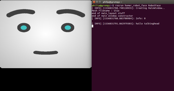
open another terminal and enter the following command:
$ rqt_graph
The graph reveals that the node subscribes to several topics, including:
- /robot_face/talking_finished - Send a message on this topic to indicate speech generation is complete
- /robot_face_expected_input - Display a status message below the face using this topic
- /robot_face_image_display - Not utilized in the EaseRobot project
- /robot_face_ImageFileDisplay - Not utilized in the EaseRobot project
- /robot_face/text_out - Animate the mouth and display text below the face using this topic; embed smileys to change facial expressions
- /recognized/speech - Not utilized in the EaseRobot project
Let's use rostopic to demonstrate these interactions. In a terminal, execute the following commands:
$ rostopic pub -1 /robot_face/expected_input std_msgs/String "Battery Low"
You should see the status message displayed below the face.
$ rostopic pub -1 /robot_face/text_out std_msgs/String "Hello my name is EaseRobot:)"
You should see the text below the face (minus the smiley), the face should animate the speech, and change from the neutral expression to a happy expression.
Now, send the following command to indicate speech completion:
$ rostopic pub -1 /robot_face/talking_finished std_msgs/String "q"
Note that the contents of this string are irrelevant, but sending this message is necessary for the face to respond to another /robot_face/text_out message.
In the /robot_face/text_out message, we changed the expression using a smiley ":)", which is one of the available options:
- "." Neutral
- ":)" Happy
- ":(" Sad
- ">:" Angry
- ":!" Disgusted
- ":&" Frightened
- ":O" or ":o" Surprised
We'll revisit the robot face node when we integrate it into our EaseRobot system.
Giving EaseRobot a Voice
Now that we've installed the robot face package, we'll also have the MARY TTS System installed. However, we'll be creating a ROS node that utilizes the more straightforward pico2wav TTS system. Our node will employ pico2wav to generate a temporary wav file, which will then be played back. Additionally, we'll add functionality to play existing short wav files.
Our ROS package for the node is called speech and is located in the speech folder. The package contains all the standard ROS files and folders.
The cfg folder contains the file speech.cfg. This file is utilized by the dynamic reconfiguration server, enabling us to adjust certain wav playback parameters in real-time. We previously used the dynamic reconfiguration server in part 1 of the article to trim the servos. This file contains the following Python code.
#!/usr/bin/env python
PACKAGE = "speech"

from dynamic_reconfigure.parameter_generator_catkin import *

gen = ParameterGenerator()

gen.add("pitch",  int_t,    0, "Playback Pitch",  -300,  -1000, 1000)
gen.add("vol",    double_t, 0, "Playback volume", 0.75, 0,   1)
gen.add("bass",   int_t,    0, "Bass",            0, -10, 10)
gen.add("treble", int_t,   0, "Treble",          0, -10, 10)
gen.add("norm",   bool_t,   0, "Normalise audio", True)

lang_enum = gen.enum([ gen.const("en_US", str_t, "en-US", "English US"),
                       gen.const("en_GB", str_t, "en-GB", "English GB"),
                       gen.const("fr_FR", str_t, "fr-FR", "French"),
                       gen.const("es_ES", str_t, "es-ES", "Spanish"),
                       gen.const("de_DE", str_t, "de-DE", "German"),
                       gen.const("it_IT", str_t, "it-IT", "Italian")],
                     "An enum to set the language")

gen.add("lang", str_t, 0, "Voice language", "en-GB", edit_method=lang_enum)

exit(gen.generate(PACKAGE, "speechnode", "Speech"))
For a comprehensive understanding of the dynamic reconfiguration server, please refer to the ROS Wiki section on dynamic reconfiguration. In our file, you can see that we add six parameters to the dynamic configuration server.
The msg folder contains a definition file for a user-defined message. The file is named voice.msg and contains the following:
string text # Text to speak
string wav  # Path to file to play
The message contains two elements: text, which will contain the text to be converted into speech, and wav, which will contain a path and filename of a wav file to play. Our code will first check to see if wav contains a path, and if so, it will play the wav file. If wav is an empty string, then text will be used to create a wav file.
The include/speech and src folders contain the C++ code for the package. For this package, we have one C++ class, SpeechNode, and a main routine contained within the speech_node.cpp file.
The main routine initializes our node, creates an instance of our class that contains the code for the node, sets up a callback function for the dynamic reconfiguration server, and creates a ros::Rate variable to control the loop frequency at 10Hz. Inside the loop, we call the speakingFinished function, which will be described later in this article.
The loop continues to execute as long as ros::ok() returns true. It will return false when the node is shutting down, such as when you press Ctrl-c on the keyboard.
Here is the C++ code for the main function:
int main(int argc, char **argv)
{
    ros::init(argc, argv, "speech_node");

    SpeechNode *speech_node = new SpeechNode();

    dynamic_reconfigure::Server<speech::SpeechConfig> server;
    dynamic_reconfigure::Server<speech::SpeechConfig>::CallbackType f;

    f = boost::bind(&SpeechNode::reconfCallback, speech_node, _1, _2);
    server.setCallback(f);

    std::string node_name = ros::this_node::getName();
    ROS_INFO("%s started", node_name.c_str());

    ros::Rate r(speech_node->LOOP_FREQUENCY_);

    while(ros::ok())
    {
        speech_node->speakingFinished();

        ros::spinOnce();
        r.sleep();
    }

    return 0;
}
The constructor for our class subscribes to the /speech/to_speak topic to receive text to speak or the location of the wav file to play. It also advertises that it will publish the /robot_face/talking_finished topic, which informs the face that the talking has finished.
Here is the C++ code for the constructor:
SpeechNode::SpeechNode()
{
    voice_sub_ = n_.subscribe("/speech/to_speak", 5, &SpeechNode::voiceCallback, this);

    talking_finished_pub_ = n_.advertise<std_msgs::String>("/robot_face/talking_finished", 5);

    finished_speaking_ = false;
}
Now, let's briefly describe the functions that make up the class.
The reconfCallback function is called by the dynamic reconfiguration server when any of the parameters are changed. This function simply stores the new values for use in the next playback of the temporary speech wav file.
Here is the C++ code for the reconfCallback function:
void SpeechNode::reconfCallback(speech::SpeechConfig &config, uint32_t level)
{
    language_ = config.lang;
    vol_ = config.vol;
    pitch_ = config.pitch;
    bass_ = config.bass;
    treble_ = config.treble;
    norm_ = config.norm;
}
The voiceCallback function is called when a message on the /speech/to_speak topic is received. If the wav element of the message is not empty, then the supplied wav filename is played using sox (Sound eXchange). Note that since we want to playback an already existing wav file and not speak in our robot's voice, none of the dynamic reconfiguration parameters are used.
If the wav element is empty, then the string in the text element is to be spoken. We start by constructing a string for the call to pico2wav, which includes our temporary filename and the language parameter. The call to pico2wav should result in the creation of a wav file without text converted to speech. A string is then constructed to be used in making a system call to sox, this time using the dynamic reconfiguration parameters so that we can control the sound of the robot's voice. For example, pico2wav only contains a female voice, but by changing the pitch, we can give the robot a male voice (which we want since ours is called EaseRobot).
The voiceCallback function finishes by setting a flag to indicate that we need to send a message on the /robot_face/talking_finished topic. We also set a countdown counter value, which is used to time 20 executions of the control loop before the /robot_face/talking_finished message is sent.
Here is the C++ code for the voiceCallback function:
void SpeechNode::voiceCallback(const speech::voice& voice)
{
    // Check if we have a path to a stock wav file
    if(voice.wav!= "")
    {
        // Play stock wav file using sox (Sound eXchange)
        std::string str = "play " + voice.wav + " --norm -q";
        ROS_DEBUG("%s", str.c_str());

        if(system(str.c_str())!= 0)
        {
            ROS_DEBUG("SpeechNode: Error on wav playback");
        }
    }
    else
    {
        std::string filename = "/tmp/robot_speech.wav";

        std::string str;

        // Create wav file using pico2wav from adjusted text
        str = "pico2wave --wave=" + filename + " --lang=" +
               language_ + " \"" + voice.text + "\"";

        ROS_DEBUG("%s", str.c_str());

        if(system(str.c_str())!= 0)
        {
            ROS_DEBUG("SpeechNode: Error on wav creation");
        }
        else
        {
            // Play created wav file using sox play with parameters bass,
            // treble, pitch, and vol
            std::string bass = " bass " + std::to_string(bass_);
            std::string treble = " treble " + std::to_string(treble_);
            std::string pitch = " pitch " + std::to_string(pitch_);

            if(norm_ == true)
            {
                str = "play " + filename + " --norm -q" + pitch + bass + treble;
            }
            else
            {
                std::string volume = " vol " + std::to_string(vol_);
                str = "play " + filename + " -q" + pitch + bass + treble + volume;
            }

            ROS_DEBUG("%s", str.c_str());

            if(system(str.c_str())!= 0)
            {
                ROS_DEBUG("SpeechNode: Error on wav playback");
            }
        }
    }

    // Set up to send talking finished
    finished_speaking_ = true;
    loop_count_down_ = (int)(LOOP_FREQUENCY_ * 2);
}
The speakingFinished function is called by the control loop in main. If we have kicked off the playback of either a wav file that already exists or our temporary wav file of text to speak, the function will count down each time it is called. When the counter reaches zero, the talking finished message is published. This gives the robot face node 2 seconds to animate the face before the finished speaking message is sent. You can increase this time if you find your robot has a lot to say, but bear in mind that the pico2wav is intended for use with a limited number of characters for text-to-speech conversion.
// If finshed speaking delay until the /robot_face/talking_finished topic is published
void SpeechNode::speakingFinished()
{
    if(finshed_speaking_ == true)
    {
        loop_count_down_--;

        if(loop_count_down_ <= 0)
        {
            finshed_speaking_ = false;

            // Send talking finished
            std_msgs::String msg;
            msg.data = "";
            talking_finished_pub_.publish(msg);
        }
    }
}
Face and Voice Integration
In our next tutorial, we will integrate the nodes from Goal 1 and Goal 2, along with a state machine package, to control the robot's missions. For now, let's test the robot's face with our speech node.
Our ROS package for the test node is called ease_robot_voice_test and is available in the ease_robot_voice_test folder.
The include/ease_robot_voice_test and src folders contain the C++ code for the package. For this package, we have one C++ class, EaseRobotVoiceTestNode, and a main routine contained within the ease_robot_voice_test_node.cpp file.
The main routine informs ROS of our node, creates an instance of the class for the node, and passes it the node handle, logs that the node has started, and hands control to ROS with the call to ros::spin.
int main(int argc, char **argv)
{
ros::init(argc, argv, "ease_robot_voice_test");
ros::NodeHandle n;
EaseRobotVoiceTestNode ease_test_node(n);
std::string node_name = ros::this_node::getName();
ROS_INFO("%s started", node_name.c_str());
ros::spin();
return 0;
}
We will use a keyboard node, available from https://github.com/lrse/ros-keyboard, to interact with the system. In the constructor, we subscribe to the topic keyboard/keydown and call the function keyboardCallBack when a message is received on that topic.
The constructor also advertises that the node will publish the topics for the speech and robot face node.
EaseRobotVoiceTestNode::EaseRobotVoiceTestNode(ros::NodeHandle n)
{
nh_ = n;

// Subscribe to receive keyboard input
key_sub_ = nh_.subscribe("keyboard/keydown", 100,
           &EaseRobotVoiceTestNode::keyboardCallBack, this);

// Advertise the topics we publish
speech_pub_ = nh_.advertise<speech::voice>("/speech/to_speak", 5);
face_status_pub_ = nh_.advertise<std_msgs::String>("/robot_face/expected_input", 5);
text_out_pub_ = nh_.advertise<std_msgs::String>("/robot_face/text_out", 5);

}
The function keyboardCallBack checks the received message for one of three keys. If the lower case's' is pressed, we test the status display functionality by creating a message and publishing it on the /robot_face/expected_input topic.
If the lower case 't' is pressed, we test the speech and speech animation by creating two messages, one that contains the text to speak and the other contains the text to animate the robot face. Note how we add the ':)' smiley to the greeting variable after we have used it to create the text to speak message, we don't want pico2wav trying to speak this as part of the text. We then publish the two messages, one to the face and the other to the speech node.
If the lower case 'w' is pressed, we test the wav file playback and speech animation again by creating two messages. This time, the message going to the speech node contains the path to a wav file instead of the text to speak. Notice however the message to the robot face still contains text to match the contents of the wav file so that the face is still animated during playback.
void EaseRobotVoiceTestNode::keyboardCallBack(const keyboard::Key::ConstPtr& msg)
{
// Check no modifiers apart from num lock is excepted
if((msg->modifiers & ~keyboard::Key::MODIFIER_NUM) == 0)
{
// Lower case
if(msg->code == keyboard::Key::KEY_s)
{
// Test status display
std_msgs::String status_msg;
status_msg.data = "EaseRobot on line";
face_status_pub_.publish(status_msg);
}
else if(msg->code == keyboard::Key::KEY_t)
{
// Test speech and animation

        // String to send to robot face
        std_msgs::String greeting;
        greeting.data = "Hello my name is EaseRobot";

        // Voice message
        speech::voice voice_msg;
        voice_msg.text = greeting.data;
        voice_msg.wav = "";

        // Add the smiley
        greeting.data += ":)";

        // Publish topics for speech and robot face animation
        text_out_pub_.publish(greeting);
        speech_pub_.publish(voice_msg);
    }
    else if(msg->code == keyboard::Key::KEY_w)
    {
        // Test wav playback and animation
        // String to send to robot face
        std_msgs::String greeting;
        greeting.data = "Danger Will Robinson danger:&";

        speech::voice voice_msg;
        std::string path = ros::package::getPath("ease_robot_voice_test");
        voice_msg.text = "";
        voice_msg.wav = path + "/sounds/lost_in_space_danger.wav";

        // Publish topics for sound and robot face animation
        text_out_pub_.publish(greeting);
        speech_pub_.publish(voice_msg);
    }
    else
    {
        ;
    }
}

}
The folder launch contains the file test.launch. This file will be used to launch the two nodes under test and the two test nodes from one terminal.
<?xml version="1.0"?>
<launch>
<node pkg="ease_home_robot_face" type="RobotFace" name="RobotFace" output="screen"/>
<node pkg="speech" type="speech_node" name="speech_node" output="screen"/>
<node pkg="ease_robot_voice_test" type="ease_robot_voice_test_node"
name="ease_robot_voice_test_node" output="screen" />
<node pkg="keyboard" type="keyboard" name="keyboard" output="screen" />
</launch>
Getting Started with The Code
Testing the Code
You can test the code on either a Linux PC or on the EaseRobot hardware, in this case, a Raspberry Pi.
If you're testing the code on a PC, you likely already have a speaker and amplifier built-in. However, since our EaseRobot is built around a Raspberry Pi, we need additional hardware to hear the voice playback. I've added an Adafruit Mono 2.5W Class D Audio Amplifier PAM8302 and an 8 Ohm speaker to the hardware. Simply connect this to the Pi audio jack, the speaker, and the Pi's 5V supply.
The audio amp is mounted on a small Veroboard attached to the back of the tilt arm, and the speaker is mounted on the front of the neck, just below the pan servo.
Hardware Considerations
While on the topic of hardware, I'd like to mention that when I first started running the EaseRobot face node, I encountered overheating issues with the Raspberry Pi during a heatwave. To mitigate this, I added a small heat sink and fan to the processor board. You can find a bracket to attach the fan to the Raspberry Pi in the 3D print zip folder.
System Applications
If not already installed, install the pico2wav and SoundeXchange applications using the following commands:
$ sudo apt-get install libttspico-utils
$ sudo apt-get install sox libsox-fmt-all
Building the ROS Packages
Create a workspace with the following commands:
$ mkdir -p ~/test_ws/src
$ cd ~/test_ws/
$ catkin_make
Copy the packages ease_robot_voice_test, speech, and ros-keyboard (from https://github.com/lrse/ros-keyboard) into the ~/test_ws/src folder and then build the code with the following commands:
$ cd ~/test_ws/
$ catkin_make
Check that the build completes without any errors.
Running the Code
Now we're ready to run our code. Use the launch file to start the nodes with the following commands. If no master node is running in the system, the launch command will also launch the master node, roscore.
$ cd ~/test_ws/
$ source devel/setup.bash
$ roslaunch ease_robot_voice_test test.launch
In the terminal, you should see:
- A list of parameters now in the parameter server
- A list of our nodes
- The address of the master
- Log information from our code
Two other windows will open, one with the EaseRobot face and a second that, when given focus, will input keyboard strokes.
In a second terminal, run the following command to start rqt_graph:
$ rqt_graph
From the graph, you should see the nodes under test and the test nodes running. You should also see the nodes linked by the topics. Any broken links indicate misspelled topics in the code.
The EaseRobot face will currently have a neutral expression. Run the following tests:
- Make sure the keyboard window has focus and press the's' key.
- The status message will appear below the face.
- Make sure the keyboard window has focus and press the 't' key.
- The EaseRobot voice will be heard, and the EaseRobot face mouth will be animated. It will end with a happy expression.
- Make sure the keyboard window has focus and press the 'w' key.
- The wav file playback will be heard, and the EaseRobot face mouth will be animated. It will end with a frightened expression.
Next, you can adjust the playback parameters of the voice. In a terminal, start rqt_reconfigure with the following command:
rosrun rqt_reconfigure rqt_reconfigure
This will bring up a user interface like the one shown below. Adjust the parameters, give the keyboard window focus, and press 't' to hear the difference.
Once you're happy with the values, you can edit the speech.cfg to include the values as the defaults. Then, the next time the speech node starts, these values will be used. Note that although the speech.cfg file is Python, you must re-make the package for the changes to take effect.
To terminate the nodes, hit Ctrl-c in the terminal.
If you've run the EaseRobot face node on the Raspberry Pi, you may have noticed that the face is not central to the screen. The flavor of Ubuntu (Lubuntu) I'm running on EaseRobot uses openbox for controlling the GUI. By editing.config/openbox/lubuntu-rc.xml and adding the following to the file, the EaseRobot Face is displayed in the center of the screen when it launches.
<application name="EaseRobotFace">
<position force="yes">
<x>200</x>
<y>0</y>
</position>
</application>

</applications>

</openbox_config>
Summary
In this segment, we've successfully infused EaseRobot with facial expressions and speech capabilities, thereby achieving our Design Goal 2.
Stay tuned for the next installment, where we'll delve into the state machine package that will orchestrate EaseRobot's mission control. We'll also explore the code that enables manual robot navigation and put it to the test on both the physical robot hardware and a simulated robot environment.
Introduction
Welcome to the fourth part of our EaseRobot project series, where we're designing and building an autonomous house bot using the Robot Operating System (ROS). In this installment, we'll introduce a state machine package and develop two nodes to control the robot's missions and tasks.
Background
In our previous articles, we defined the requirements for our EaseRobot project and broke down our first mission into manageable design goals. Our mission, inspired by the "Let's build a robot!" article, is to create a robot that can take messages to family members.
The design goals for this mission are:
- Visual Recognition: Use the camera to search for faces, identify people, and display a message for recognized individuals.
- Facial Expressions and Speech Synthesis: Enable the EaseRobot to deliver messages with facial expressions and speech synthesis.
- Remote Control: Control the robot's locomotion using a remote keyboard and/or joystick.
- Sensor Integration: Add a laser ranger finder or similar ranging sensor to aid navigation.
- Autonomous Locomotion: Enable the EaseRobot to move independently.
- Task Management: Assign and notify tasks to the EaseRobot.
In our previous articles, we completed Design Goals 1 and 2. In this installment, we'll introduce a state machine package and develop two nodes to control the robot's missions and tasks, bringing us closer to achieving our design goals.
A Sophisticated Plan for EaseRobot
Introducing SMACH
As we prepare to integrate our design goals, we'll need a complex system to orchestrate and control the various components of EaseRobot. To achieve this, we'll utilize SMACH, a ROS Python library that enables the development of hierarchical state machines. The SMACH package documentation is available on the ROS Wiki website.
Unifying Design Goals 1 and 2
Although our ultimate objective is Mission 1, we'll start by combining Design Goals 1 and 2 into a smaller mission, Mission 2. This mission will focus on searching for recognized faces within the head movement range and speaking a greeting to anyone the robot recognizes. The processes developed for Mission 2 will later be incorporated into Mission 1.
To complete Mission 2, we'll create two nodes: ease_robot_missions and ease_robot. The ease_robot_missions node will contain the code for the state machine, managing missions and jobs. The ease_robot node will control when missions and jobs are initiated. We'll also add functionality for reading keyboard and game controller inputs, which will be used in Design Goal 3.
Introducing Jobs
In addition to missions, we'll introduce the concept of "jobs," which are tasks the robot needs to perform that are less complex than full missions. The node running the state machines is the ideal place for these jobs, as they may require the same resources as the more complex missions.
EaseRobot State Machine
We'll begin with the package and node containing the state machine that controls EaseRobot's missions and jobs. Since SMACH is a Python library, our package will be written in Python.
Our ROS package for the node is called ease_robot_missions and is available in the ease_robot_missions folder. The src folder contains the ease_robot_missions_node.py file, which holds the main code for the node. The src folder also contains a subfolder called missions_lib, where each of EaseRobot's missions will result in a Python file. We'll focus on Mission 2, with the code located in the greet_all.py file.
The ease_robot_missions_node.py file will contain code to register the node, helper functions, and the high-level state machine that accepts each mission and job. The greet_all.py file will contain the sub-state machine for Mission 2. As we add new missions to EaseRobot, we'll create sub-state machines for each mission.
The diagram below illustrates our current state machine.
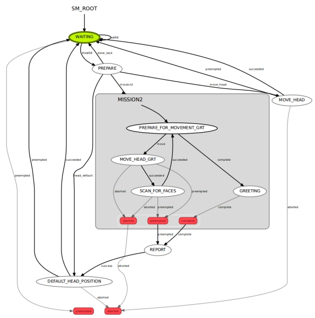
In this section, we'll delve into the intricacies of the EaseRobot state machine, which is responsible for managing the robot's missions and jobs.
WAITING State
The WAITING state is a specialized MonitorState that continuously monitors the /missions/mission_request topic. When a message is received, it extracts the request and associated parameters, then transitions to the PREPARE state, passing on the request data.
PREPARE State
The PREPARE state handles 'Job' requests, which may involve transitioning to the MOVE_HEAD, DEFAULT_HEAD_POSITION, or WAITING states. If the request is to execute Mission 2, it transitions to the MISSION2 sub-state machine.
MOVE_HEAD State
The MOVE_HEAD state is a SimpleActionState that sends a request to move the head/camera to a specified position. Once the move is complete, it transitions to the WAITING state.
DEFAULT_HEAD_POSITION State
The DEFAULT_HEAD_POSITION state is also a SimpleActionState, but it only moves the head/camera to the default position. Once the move is complete, it transitions to the WAITING state.
REPORT State
The REPORT state sends a mission complete message on the /missions/mission_complete topic and transitions to the DEFAULT_HEAD_POSITION state.
PREPARE_FOR_MOVEMENT_GRT State
This state calculates the next head position and determines if there are still scans to be done. If so, it transitions to the MOVE_HEAD_GRT state; otherwise, it transitions to the GREETING state.
MOVE_HEAD_GRT State
The MOVE_HEAD_GRT state is a SimpleActionState that requests the head/camera to move to the calculated position, then transitions to the SCAN_FOR_FACES state.
SCAN_FOR_FACES State
The SCAN_FOR_FACES state is a SimpleActionState that requests a scan for known faces in the current camera image. If faces are recognized, the names are stored for later use, and the state transitions to the PREPARE_FOR_MOVEMENT_GRT state.
GREETING State
The GREETING state requests a greeting to be spoken for all recognized individuals, then transitions to the REPORT state.
/missions/mission_request Topic The /missions/mission_request topic contains a string message with an ID for the Mission or Job, followed by zero or more parameters separated by the '^' character.
Currently, the IDs and parameters are as follows:
- "M2" - Request to conduct Mission 2 (no parameters)
- "J1" - Request to conduct Job 1 (parameters: wav file name and matching text)
- "J2" - Request to conduct Job 2 (parameters: text to speak and matching text)
- "J3" - Request to conduct Job 3 (parameters: head movement direction and camera position)
The Code
We'll now explore the code, starting with the ease_robot_missions_node.py file, which contains the main function, the top-level state machine class, state classes, and a helper function class used by the various states.
The primary function registers our node with ROS and creates an instance of the EaseRobotMissionsNode class.
def main(args):
    rospy.init_node('ease_robot_missions_node', anonymous=False)
    rospy.loginfo("EaseRobot missions node started")
    erm = EaseRobotMissionsNode()
The class constructor for EaseRobotMissionsNode sets up to call ShutdownCallback if the node is shutdown. It then subscribes to the /missions/mission_cancel topic, supplying the callback CancelCallback. Next, it creates an instance of the helper class. It then creates the states of the top-level state machine and adds them to the state machine. At this level, the MISSION 2 sub-state machine is a single state in our top-level state machine.
We then create and start an introspective server. This is not required for the robot to operate but allows you to run a tool called smach_viewer. This tool can help to debug any problems with your state machine and was used to automatically produce the state machine diagram above.
The constructor then starts the execution of the state machine and hands control over to ROS.
There are three other functions in the EaseRobotMissionsNode class.
- MissionsRequestCB is the function called by the MonitorState WAITING when a message is received on the /missions/mission_request topic. This extracts the data from the message and copies it to userdata, which is a process for passing data between states. It then returns False so that the state machine will transit to the PREPARE state.
- CancelCallback is the callback function called if a message is received on the /missions/mission_cancel topic. This will result in the pre-emption of our lower state machine if it is running.
- ShutdownCallback is the callback function called if the node receives a command from ROS to shutdown.
# Top level state machine. The work for each mission is another state machine
# in the 'mission' states
class EaseRobotMissionsNode:
    def __init__(self):
        rospy.on_shutdown(self.ShutdownCallback)

        # Subscribe to message to cancel missions
        self.__cancel_sub = rospy.Subscriber('/missions/mission_cancel', Empty,
                                             self.CancelCallback)

        # Create an instance of the missions helper class
        self.__missions_helper = MissionsHelper()

        # ------------------------- Top level state machine -------------------------
        # Create top level state machine
        self.__sm = StateMachine(outcomes=['preempted','aborted'],
                                 output_keys=['mission_data'])
        with self.__sm:
            # Add a state which monitors for a mission to run
            StateMachine.add('WAITING',
                             MonitorState('/missions/mission_request',
                             String,
                             self.MissionRequestCB,
                             output_keys = ['mission']),
                             transitions={'valid':'WAITING', 'invalid':'PREPARE',
                                          'preempted':'preempted'})

            # Add state to prepare the mission
            StateMachine.add('PREPARE',
                             Prepare(self.__missions_helper),
                             transitions={'mission2':'MISSION2',
                                          'done_task':'WAITING',
                                          'head_default':'DEFAULT_HEAD_POSITION',
                                          'move_head':'MOVE_HEAD'})

            # Add the reporting state
            StateMachine.add('REPORT',
                             Report(),
                             transitions={'success':'DEFAULT_HEAD_POSITION'})

            # Set up action goal for deafult head position
            default_position_pan, default_position_tilt =
                                  self.__missions_helper.CameraDefaultPos()
            head_goal = point_headGoal()
            head_goal.absolute = True
            head_goal.pan = default_position_pan
            head_goal.tilt = default_position_tilt

            # Add the default camera position state.
            # Which moves the head to the default position
            StateMachine.add('DEFAULT_HEAD_POSITION',
                             SimpleActionState('head_control_node',
                                               point_headAction,
                                               result_cb =
                                               self.__missions_helper.CameraAtDefaultPos,
                                               goal = head_goal),
                             transitions={'succeeded':'WAITING','preempted':'WAITING',
                                          'aborted':'aborted'})

            # Add the move head state
            StateMachine.add('MOVE_HEAD',
                             SimpleActionState('head_control_node',
                                               point_headAction,
                                               goal_slots=['absolute', 'pan', 'tilt']),
                             transitions={'succeeded':'WAITING', 'preempted':'WAITING',
                                          'aborted':'aborted'},
                             remapping={'absolute':'user_data_absolute', 'pan':'user_data_pan',
                                        'tilt':'user_data_tilt'})

            # ------------------------- Sub State machine for mission 2 ---------------------
            # Create a sub state machine for mission 2 - face detection and greeting
            self.__sm_mission2 = missions_lib.Mission2StateMachine(self.__missions_helper)

            # Now add the sub state machine for mission 2 to the top level one
            StateMachine.add('MISSION2',
                             self.__sm_mission2,
                             transitions={'complete':'REPORT','preempted':'REPORT',
                                          'aborted':'aborted'})
            # -------------------------------------------------------------------------------

        # Create and start the introspective server so that we can use smach_viewer
        sis = IntrospectionServer('server_name', self.__sm, '/SM_ROOT')
        sis.start()

        self.__sm.execute()

        # Wait for ctrl-c to stop application
        rospy.spin()
        sis.stop()

    # Monitor State takes /missions/mission_request topic and passes the mission
    # in user_data to the PREPARE state
    def MissionRequestCB(self, userdata, msg):
        # Take the message data and send it to the next state in the userdata
        userdata.mission = msg.data

        # Returning False means the state transition will follow the invalid line
        return False

    # Callback for cancel mission message
    def CancelCallback(self, data):
        # If a sub statemachine for a mission is running then request it be preempted
        if self.__sm_mission2.is_running():
            self.__sm_mission2.request_preempt()

    def ShutdownCallback(self):
        self.__sm.request_preempt()
        # Although we have requested to shutdown the state machine
        # it will not happen if we are in WAITING until a message arrives
the PREPARE and REPORT states are encapsulated within separate classes in the EaseRobot_missions_node.py file.
The Prepare class is designed with a constructor that defines the subsequent state following PREPARE, specifies the data to be passed to it, and stores an instance of the helper class.
Upon entering the state, the execute function is triggered, which examines the request message, executes any feasible jobs, and subsequently transitions to the WAITING state or redirects to another state to execute the job or mission.
# The PREPARE state
class Prepare(State):
    def __init__(self, helper_obj):
        State.__init__(self, outcomes=['mission2','done_task','head_default','move_head'],
                       input_keys=['mission'],
                       output_keys=['mission_data','start',
                       'user_data_absolute','user_data_pan','user_data_tilt'])
        self.__helper_obj = helper_obj

    def execute(self, userdata):
        # Based on the userdata either change state to the required mission or
        # carry out single job userdata.mission contains the mission or single
        # job and a number of parameters seperated by '^'
        retVal = 'done_task';

        # Split into parameters using '^' as the delimiter
        parameters = userdata.mission.split("^")

        if parameters[0] == 'M2':
            # Mission 2 is scan for faces and greet those known, there are no
            # other parameters with this mission request
            userdata.start = True
            retVal = 'mission2'
        elif parameters[0] == 'J1':
            # Simple Job 1 is play a supplied wav file and move the face lips
            # Publish topic for speech wav and robot face animation
            self.__helper_obj.Wav(parameters[1], parameters[2])
        elif parameters[0] == 'J2':
            # Simple Job 2 is to speak the supplied text and move the face lips
            # Publish topic for speech and robot face animation
            self.__helper_obj.Speak(parameters[1], parameters[2])
        elif parameters[0] == 'J3':
            # Simple Job 3 is to move the head/camera. This command will only
            # be sent in manual mode.
            # parameters[1] will either be 'u', 'd', 'c' or '-'
            # parameters[2] will either be 'l', 'r' or '-'
            # Check for return to default command
            if 'c' in parameters[1]:
                retVal = 'head_default'
            else:
                relative_request_pan, relative_request_tilt =
                         self.__helper_obj.CameraManualMove(parameters[1]+parameters[2])
                # Set up user data that will be used for goal in next state
                userdata.user_data_absolute = False # This will be a relative move
                userdata.user_data_pan = relative_request_pan
                userdata.user_data_tilt = relative_request_tilt
                retVal = 'move_head'

        return retVal
The Report class is designed to facilitate the REPORT state, which is responsible for publishing a message on the /missions/mission_complete topic upon completion of a mission.
The class constructor initializes the REPORT state, specifying the outcome as'success' and establishing a publisher for the /missions/mission_complete topic.
When the REPORT state is entered, the execute function is triggered, publishing a message indicating that the mission has been completed.
class Report(State):
def init(self):
State.init(self, outcomes=['success'])
self.publisher = rospy.Publisher('/missions/mission_complete', String, queue_size=5)

def execute(self, userdata):
    # Publishes message signaling mission completion
    self.publisher.publish("Mission Complete")
    return'success'
The EaseRobot_missions_node.py file also includes the MissionHelper class, which serves as a utility class for various missions. This class provides reusable code for the sub-state machines, eliminating the need for code duplication. The functions within this class enable communication with the voice and robot face nodes, as well as calculating the next position of the head/camera.
# Helper class to hold code used by serveral different states
class MissionsHelper():
    def __init__(self):
        self.__speech_pub_ = rospy.Publisher('/speech/to_speak', voice, queue_size=1)
        self.__text_out_pub = rospy.Publisher('/robot_face/text_out', String, queue_size=1)

        # Obtain values from the parameter server
        # Minium/Maximum range movment of camera
        self.__pan_min = rospy.get_param("/servo/index0/pan/min", -(pi/2.0))
        self.__pan_max = rospy.get_param("/servo/index0/pan/max", pi/2.0)
        self.__tilt_min = rospy.get_param("/servo/index0/tilt/min", -(pi/2.0))
        self.__tilt_max = rospy.get_param("/servo/index0/tilt/max", pi/2.0);
        # Default position after mission ends
        self.__camera_default_pan_position = rospy.get_param("/head/position/pan", 0.0)
        self.__camera_default_tilt_position = rospy.get_param("/head/position/tilt", 0.0)
        # Step value to move the camera by when searching
        self.__pan_step_value = rospy.get_param("/head/view_step/pan", 0.436332)
        self.__tilt_step_value = rospy.get_param("/head/view_step/tilt", 0.436332)
        # Step value to move the camera in manual mode
        self.__manual_pan_step_value = rospy.get_param("/head/manual_view_step/pan", 0.174533)
        self.__manual_tilt_step_value = rospy.get_param("/head/manual_view_step/tilt", 0.174533)

        # When true and scanning pan angle will increase, otherwise decrease
        self.__increase_pan = True

        # Position that will be requested to move the head/camera to
        self.__position_request_pan = self.__camera_default_pan_position
        self.__position_request_tilt = self.__camera_default_tilt_position

    def Speak(self, text_to_speak, text_to_display):
        voice_msg = voice()
        voice_msg.text = text_to_speak
        voice_msg.wav = ""

        # Publish topic for speech and robot face animation
        self.__speech_pub_.publish(voice_msg)
        self.__text_out_pub.publish(text_to_display)

    def Wav(self, wav_file, text_to_display):
        voice_msg = voice()
        voice_msg.text = ""
        voice_msg.wav = wav_file

        # Publish
        self.__speech_pub_.publish(voice_msg)
        self.__text_out_pub.publish(text_to_display)

    # Function to return the camera start position when scanning within head movement range
    def CameraToStartPos(self):
        # Set the camera position to pan min and tilt min
        self.__position_request_pan = self.__pan_min
        self.__position_request_tilt = self.__tilt_max
        # Set the variable that says which direction the pan is going. Start by incrementing
        self.__increase_pan_ = True
        return self.__position_request_pan, self.__position_request_tilt

    # Function to keep track of position after action to set to default position
    def CameraAtDefaultPos(self, userdata, status, result):
        if status == GoalStatus.SUCCEEDED:
            self.__position_request_pan = self.__camera_default_pan_position
            self.__position_request_tilt = self.__camera_default_tilt_position

    # Function returns camera default position
    def CameraDefaultPos(self):
        return self.__camera_default_pan_position, self.__camera_default_tilt_position

    # Function to return the next position when scanning within the head movement range.
    # Also returns indication if all areas scanned or more left
    def CameraToNextPos(self):
        all_areas_scanned = False
        # Calculate the next position of the head/camera
        if self.__increase_pan == True:
            if self.__position_request_pan == self.__pan_max:
                # Last scan was at the edge, move tilt up and then pan the other way
                self.__increase_pan = False
                self.__position_request_tilt -= self.__tilt_step_value

                if self.__position_request_tilt < self.__tilt_min:
                    all_areas_scanned = True
            else:
                self.__position_request_pan += self.__pan_step_value

                if self.__position_request_pan > self.__pan_max:
                    # Moved out of range, put back on max
                    self.__position_request_pan = self.__pan_max
        else:
            if self.__position_request_pan == self.__pan_min:
                # Last scan was at the edge, move tilt up and then pan the other way
                self.__increase_pan = True
                self.__position_request_tilt -= self.__tilt_step_value

                if self.__position_request_tilt < self.__tilt_min:
                    all_areas_scanned = True
            else:
                self.__position_request_pan -= self.__pan_step_value

                if self.__position_request_pan < self.__pan_min:
                    # Moved out of range, put back on min
                    self.__position_request_pan = self.__pan_min

        if all_areas_scanned == True:
            # Reset camera/head position to default values
            self.__position_request_pan = self.__camera_default_pan_position
            self.__position_request_tilt = self.__camera_default_tilt_position

        return all_areas_scanned, self.__position_request_pan, self.__position_request_tilt

    def CameraManualMove(self, direction):
        relative_request_pan = 0.0
        relative_request_tilt = 0.0
        # Check for up command
        if 'd' in direction:
            relative_request_tilt = self.__manual_tilt_step_value
            if (self.__position_request_tilt + relative_request_tilt) > self.__tilt_max:
                # Would move out of range so move to the max position
                relative_request_tilt = self.__tilt_max - self.__position_request_tilt
                self.__position_request_tilt = self.__tilt_max
            else:
                # Keep track
                self.__position_request_tilt += relative_request_tilt

        # Check for down command
        if 'u' in direction:
            relative_request_tilt = -(self.__manual_tilt_step_value)
            if (self.__position_request_tilt + relative_request_tilt) < self.__tilt_min:
                # Would move out of range so move to the min position
                relative_request_tilt = self.__tilt_min - self.__position_request_tilt
                self.__position_request_tilt = self.__tilt_min
            else:
                # Keep track
                self.__position_request_tilt += relative_request_tilt

        # Check for left commnand
        if 'l' in direction:
            relative_request_pan = self.__manual_pan_step_value
            if (self.__position_request_pan + relative_request_pan) > self.__pan_max:
                # Would move out of range so move to the max
                relative_request_pan = self.__pan_max - self.__position_request_pan
                self.__position_request_pan = self.__pan_max
            else:
                # Keep track
                self.__position_request_pan += relative_request_pan

        # Check for right command
        if 'r' in direction:

            relative_request_pan = -(self.__manual_pan_step_value)
            if (self.__position_request_pan + relative_request_pan) < self.__pan_min:
                # Would move out of range so so move to min
                relative_request_pan = self.__pan_min - self.__position_request_pan
                self.__position_request_pan = self.__pan_min
            else:
                # Keep track
                self.__position_request_pan += relative_request_pan

        return relative_request_pan, relative_request_tilt
the missions_lib subfolder serves as a repository for sub-state machines dedicated to various missions. Currently, the mission 2 sub-state machine is implemented in the greet_all.py file.
The primary class in this file is Mission2StateMachine, which inherits from the StateMachine parent class. The constructor initializes the sub-state machine, stores an instance of the helper class, and creates each state that comprises this sub-state machine. Additionally, the class features a callback function that is triggered when the face recognition action returns its result, enabling seamless integration with the mission workflow.
# Child (derived) class. Parent class is StateMachine
class Mission2StateMachine(StateMachine):
    def __init__(self, helper_obj):
        StateMachine.__init__(self, outcomes=['complete','preempted','aborted'],
                              input_keys=['start'])

        self.__helper_obj = helper_obj

        with self:
            # This state will calculate the next head/camera position
            StateMachine.add('PREPARE_FOR_MOVEMENT_GRT',
                             PrepareMovementGeeting(self.__helper_obj),
                             transitions={'complete':'GREETING','move':'MOVE_HEAD_GRT'},
                             remapping={'start_in':'start','start_out':'start'})

            # This state will call the action to move the head/camera
            StateMachine.add('MOVE_HEAD_GRT',
                             SimpleActionState('head_control_node',
                                               point_headAction,
                                               goal_slots=['absolute','pan','tilt']),
                             transitions={'succeeded':'SCAN_FOR_FACES',
                                          'preempted':'preempted','aborted':'aborted'},
                             remapping={'absolute':'user_data_absolute',
                                        'pan':'user_data_pan','tilt':'user_data_tilt'})

            # This state will call the action to scan for faces on the image from the camera
            StateMachine.add('SCAN_FOR_FACES',
                             SimpleActionState('face_recognition',
                                               scan_for_facesAction,
                                               result_cb=self.face_recognition_result_cb,
                                               input_keys=['seen_dict_in'],
                                               output_keys=['seen_dict_out']),
                              remapping={'seen_dict_in':'seen_dict',
                                         'seen_dict_out':'seen_dict'},
                              transitions={'succeeded':'PREPARE_FOR_MOVEMENT_GRT',
                                           'preempted':'preempted','aborted':'aborted'})

            StateMachine.add('GREETING',
                             Greeting(self.__helper_obj),
                             transitions={'complete':'complete'})

    def face_recognition_result_cb(self, userdata, status, result):
        if status == GoalStatus.SUCCEEDED:
            # Face recognition action complete
            local_dict = userdata.seen_dict_in
            if len(result.ids_detected) > 0:
                # Recognised faces detected. Have we seen them before or are they new
                for idx, val in enumerate(result.ids_detected):
                    if val not in local_dict:
                        # Add to dictionary
                        local_dict[val] = result.names_detected[idx]

                        # Log who was seen
                        rospy.loginfo("Greeting: I have seen %s", result.names_detected[idx])

                # Update disctionary stored in user data
                userdata.seen_dict_out = local_dict

        # By not returning anything the state will return with the
        # corresponding outcome of the action
Furthermore, the greet_all.py file encompasses two additional classes that constitute the core of the PREPARE_FOR_MOVEMENT_GRT and GREETING states, respectively. These classes play a vital role in orchestrating the mission's workflow, ensuring a seamless transition between states.
# PREPARE_FOR_MOVEMENT_GRT State
class PrepareMovementGeeting(State):
    def __init__(self, helper_obj):
        State.__init__(self, outcomes=['complete','move'],
                       input_keys=['start_in'],
                       output_keys=['start_out','seen_dict',
                       'user_data_absolute','user_data_pan','user_data_tilt'])
        self.__helper_obj = helper_obj

    def execute(self, userdata):
        # Is this the start of a new mission
        if userdata.start_in == True:
            userdata.start_out = False
            # clear the seen dictionary
            userdata.seen_dict = {}
            scan_complete = False
            # get the camera start position (pan min and tilt max)
            position_request_pan,  position_request_tilt =
                                   self.__helper_obj.CameraToStartPos()
        else:
            scan_complete, position_request_pan, position_request_tilt =
                                                 self.__helper_obj.CameraToNextPos()

        # Set up user data that will be used for goal in next state if not complete
        userdata.user_data_absolute = True
        userdata.user_data_pan = position_request_pan
        userdata.user_data_tilt = position_request_tilt

        if scan_complete == True:
            next_outcome = 'complete'
        else:
            next_outcome = 'move'

        return next_outcome

# Greeting State
class Greeting(State):
    def __init__(self, helper_obj):
        State.__init__(self, outcomes=['complete'],
                       input_keys=['seen_dict'])
        self.__helper_obj = helper_obj

    def execute(self, userdata):
        # userdata.seen_dict contains a dictionary of ids and names seen
        # Construct greeting
        greeting = ''
        if len(userdata.seen_dict) == 0:
            greeting = 'No one recognised'
        else:
            greeting = 'Hello '
            for id, name in userdata.seen_dict.items():
                greeting += name + ' '

            greeting += 'how are you '

            if len(userdata.seen_dict) == 1:
                greeting += 'today'
            elif len(userdata.seen_dict) == 2:
                greeting += 'both'
            else:
                greeting += 'all'

        rospy.loginfo(greeting)

        # Speak greeting
        self.__helper_obj.Speak(greeting, greeting + ':)')

        return 'complete'
As the EaseRobot project continues to evolve, we will adopt a modular approach to incorporating new missions, where each mission will be represented by a sub-state machine added to the missions_lib library. This template-based methodology will enable efficient expansion and maintenance of the project's capabilities.
Top Level Control
The EaseRobot node is responsible for the top-level control of the robot.
Our ROS package for the node is called ease_robot and is available in the ease_robot folder. The package contains all the usual ROS files and folders, plus a few extra.
The config folder contains a config.yaml file that can be used to override some of the default configuration values. You can configure:
- the game controller axis used for moving the robot forward and backward in manual locomotion mode
- the game controller axis used for moving the robot clockwise and anti-clockwise in manual locomotion mode
- the game controller axis used for moving the head/camera up and down in manual locomotion mode
- the game controller axis used for moving the head/camera left and right in manual locomotion mode
- the game controller button used for selecting manual locomotion mode
- the game controller button used for moving the head/camera back to the default position
- the game controller axes dead zone value
- the linear velocity requested when the controller axis is at its maximum range
- the angular velocity requested when the controller axis is at its maximum range
- the ramp rate used to increase or decrease the linear velocity
- the ramp rate used to increase or decrease the angular velocity
- the battery voltage level that a low battery warning will be issued at
- enable/disable the wav file playback functionality when the robot is inactive
- a list of wav filenames to play from when the robot is inactive
- A list of speeches to use when playing the wav filesnames
The launch folder contains two launch files, ease_robot.launch and rviz.launch. The ease_robot.launch file is used to load all the configuration files, covered in the first four articles, into the parameter server and to start all the nodes that make up the robot project. It is similar to the launch files used so far in the project, except it now includes the ease_robot_node and the ease_robot_missions_node. rviz is a 3D visualization tool for ROS that can be used to visualize data, including the robot position and pose. Documentation for rviz is available on the ROS Wiki website. The rviz.launch file, along with the meshes, rviz, and urdf folders, can be used for visualizing EaseRobot. We will use the urdf model of EaseRobot to do some testing on a simulated EaseRobot robot.
The image below shows a visualization of EaseRobot in rviz.
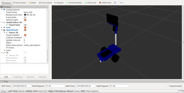
The ease_robot_control folder is just a convenient place to store the Arduino file that was discussed in Part 1.
The sounds folder is used to hold any wav files that the system is required to play. How to play these files and at the same time animate the robot face was covered in Part 3.
The include/ease_robot and src folders contain the C++ code for the package. For this package, we have one C++ class, EaseRobotNode, and a main routine contained within the ease_robot_node.cpp file.
The main routine informs ROS of our node, creates an instance of the node class, and passes it the node handle.
Again, we are going to do some processing of our own in a loop, so instead of passing control to ROS with a call to ros::spin, we are going to call ros::spinOnce to handle the transmitting and receiving of the topics. The loop will be maintained at a rate of 20Hz, which is set up by the call to ros::rate, and the timing is maintained by the call to r.sleep within the loop.
Our loop will continue while the call to ros::ok returns true, it will return false when the node has finished shutting down, e.g., when you press Ctrl-c on the keyboard.
In the loop, we will call checkTimers and sendTwist, which are described later in the article:
int main(int argc, char **argv)
{
ros::init(argc, argv, "ease_robot");
ros::NodeHandle n;
EaseRobotNode ease_robot_node(n);
std::string node_name = ros::this_node::getName();
ROS_INFO("%s started", node_name.c_str());

ros::Rate r(20); // 20Hz

while(ros::ok())
{
    ease_robot_node.sendTwist();
    ease_robot_node.checkTimers();

    ros::spinOnce();
    r.sleep();
}

return 0;

}
The constructor for our class starts by setting default values for the class parameters. For each of the parameters which are configurable using the ROS parameter server, a call is made to either param or getParam. The difference between these two calls is that with param, the default value passed to the call is used if the parameter is not available in the parameter server.
We next subscribe to the topics that the node is interested in.
- keyboard/keydown - to obtain key presses from a keyboard. These key presses are generated from a remote PC to control the robot in manual mode
- joy - to obtain joystick/game pad controller input, again to control the robot from a remote PC
- missions/mission_complete - so that the node is informed when the current robot mission is completed
- main_battery_status - this will be used later in the project to receive the state of the robots main battery
- demand_vel - this will be used later in the project to receive autonomous velocity demands
Next in the constructor is the advertisement of the topics which this node will publish.
- /robot_face/expected_input - This topic was discussed in part 3 of these articles and is used to display a status below the robot face. We will use it to show the status of the main battery
- /missions/mission_request - This will be used to pass requested missions and jobs on to the state machine node.
- /missions/mission_cancel - This can be used to cancel the current ongoing mission.
- /missions/mission_acknowledge - This will be used later in the project to acknowledge that part of a mission is complete and to continue with the rest of the mission.
- /cmd_vel - This will be used later in the project to send velocity commands to the node responsible for driving the electric motors. The requested velocities will either be from the autonomous subsystem or as a result of keyboard/joystick requests when in manual mode.
- /commands/reset_odometry - This will be used later in the project to reset the robot odometry values.
Finally, the constructor sets a random generator seed and obtains the current time. The use of the random number generator and the time is discussed in the section on the checkTimers method.
// Constructor
EaseRobotNode::EaseRobotNode(ros::NodeHandle n)
{
    nh_ = n;

    joystick_linear_speed_ = 0.0f;
    joystick_angular_speed_ = 0.0f;

    linear_mission_demand_ = 0.0f;
    angular_mission_demand_ = 0.0f;

    manual_locomotion_mode_ = false;
    linear_set_speed_ = 0.5f;
    angular_set_speed_ = 2.5f;

    // Obtain any configuration values from the parameter server.
    // If they don't exist, use the defaults above
    nh_.param("/controller/axes/linear_speed_index", linear_speed_index_, 0);
    nh_.param("/controller/axes/angular_speed_index", angular_speed_index_, 1);
    nh_.param("/controller/axes/camera_x_index", camera_x_index_, 2);
    nh_.param("/controller/axes/camera_y_index", camera_y_index_, 3);
    nh_.param("/controller/buttons/manual_mode_select", manual_mode_select_, 0);
    nh_.param("/controller/buttons/default_camera_pos_select", default_camera_pos_select_, 1);
    nh_.param("/controller/dead_zone", dead_zone_, 2000);
    nh_.param("/teleop/max_linear_speed", max_linear_speed_, 3.0f);
    nh_.param("/teleop/max_angular_speed", max_angular_speed_, 3.0f);
    nh_.param("/motor/ramp/linear", ramp_for_linear_, 5.0f);
    nh_.param("/motor/ramp/angular", ramp_for_angular_, 5.0f);
    nh_.param("/battery/warning_level", voltage_level_warning_, 9.5f);
    nh_.param("/sounds/enabled", wav_play_enabled_, false);

    // Obtain the filename and text for the wav files that can be played
    nh_.getParam("/sounds/filenames", wav_file_names_);
    nh_.getParam("/sounds/text", wav_file_texts_);

    // Subscribe to receive keyboard input, joystick input,
    // mission complete and battery state
    key_sub_ = nh_.subscribe("keyboard/keydown", 5, &EaseRobotNode::keyboardCallBack, this);
    joy_sub_ = nh_.subscribe("joy", 1, &EaseRobotNode::joystickCallback, this);
    mission_sub_ = nh_.subscribe("/missions/mission_complete", 5,
                                  &EaseRobotNode::completeCallBack, this);
    battery_status_sub_ = nh_.subscribe("main_battery_status", 1,
                                         &EaseRobotNode::batteryCallback, this);

    // The cmd_vel topic below is the command velocity message to the motor driver.
    // This can be created from either keyboard or game pad input when in manual mode
    // or from this subscribed topic when in autonomous mode.
    // It will probably be remapped from the navigation stack
    demand_sub_ = nh_.subscribe("demand_vel", 5, &EaseRobotNode::motorDemandCallBack, this);

    // Advertise the topics we publish
    face_status_pub_ = nh_.advertise<std_msgs::String>("/robot_face/expected_input", 5);
    mission_pub_ = nh_.advertise<std_msgs::String>("/missions/mission_request", 10);
    cancel_pub_ = nh_.advertise<std_msgs::Empty>("/missions/mission_cancel", 5);
    ack_pub_ = nh_.advertise<std_msgs::Empty>("/missions/acknowledge", 5);
    twist_pub_ = nh_.advertise<geometry_msgs::Twist>("cmd_vel", 1);
    reset_odom_ = nh_.advertise<std_msgs::Empty>("/commands/reset_odometry", 1);

    battery_low_count_ = 0;
    mission_running_ = false;

    // Seed the random number generator
    srand((unsigned)time(0));

    last_interaction_time_ = ros::Time::now();
}
It delves into the composition of the class, highlighting the joystickCallback function. This function is triggered when a message is received via the Joy topic, enabling the joystick or gamepad controller to navigate the robot and control the head/camera movements in manual mode.
The joystick data is organized into two arrays: one containing the current axis positions and the other storing the current button states. The specific axis and button indices used can be customized through the parameter server.
The function begins by reading the axis values that govern the robot's angular and linear velocity. These values are then compared to a deadband value, which determines the minimum axis movement required to affect the robot's control. The controller values are subsequently converted into linear and velocity demands, ensuring that the maximum possible controller value corresponds to the robot's top speed. These values are stored for later use in the sendTwist method.
Next, the function reads the axis values responsible for controlling the head/camera movements in manual mode, applying a deadband to the values. If the robot is in manual locomotion mode, the values are transmitted as a "J3" job to the EaseRobot_mission_node.
Finally, the function examines the button values, with configurable indices for each function. One button toggles manual locomotion mode, canceling any ongoing robot mission if necessary. Another button provides a quick way to reset the head/camera to its default position.
void EaseRobotNode::joystickCallback(const sensor_msgs::Joy::ConstPtr& msg)
{
    float joystick_x_axes;
    float joystick_y_axes;

    // manual locomotion mode can use the joystick/game pad
    joystick_x_axes = msg->axes[angular_speed_index_];
    joystick_y_axes = msg->axes[linear_speed_index_];

    // Check dead zone values
    if(abs(joystick_x_axes) < dead_zone_)
    {
        joystick_x_axes = 0;
    }

    if(abs(joystick_y_axes) < dead_zone_)
    {
        joystick_y_axes = 0;
    }

    // Check for manual movement
    if(joystick_y_axes != 0)
    {
        joystick_linear_speed_ = -(joystick_y_axes*(max_linear_speed_/(float)MAX_AXES_VALUE_));
        last_interaction_time_ = ros::Time::now();
    }
    else
    {
        joystick_linear_speed_ = 0;
    }

    if(joystick_x_axes != 0)
    {
        joystick_angular_speed_ =
                -(joystick_x_axes*(max_angular_speed_/(float)MAX_AXES_VALUE_));
        last_interaction_time_ = ros::Time::now();
    }
    else
    {
        joystick_angular_speed_ = 0;
    }

    // Now check the joystick/game pad for manual camera movement
    joystick_x_axes = msg->axes[camera_x_index_];
    joystick_y_axes = msg->axes[camera_y_index_];

    // Check dead zone values
    if(abs(joystick_x_axes) < dead_zone_)
    {
        joystick_x_axes = 0;
    }

    if(abs(joystick_y_axes) < dead_zone_)
    {
        joystick_y_axes = 0;
    }

    if(manual_locomotion_mode_ == true)
    {
        if((joystick_x_axes != 0) || (joystick_y_axes != 0))
        {
            std_msgs::String mission_msg;
            mission_msg.data = "J3^";

            if(joystick_y_axes == 0)
            {
                mission_msg.data += "-^";
            }
            else if (joystick_y_axes > 0)
            {
                mission_msg.data += "u^";
            }
            else
            {
                mission_msg.data += "d^";
            }

            if(joystick_x_axes == 0)
            {
                mission_msg.data += "-";
            }
            else if (joystick_x_axes > 0)
            {
                mission_msg.data += "r";
            }
            else
            {
                mission_msg.data += "l";
            }

            mission_pub_.publish(mission_msg);

            last_interaction_time_ = ros::Time::now();
        }
    }

    // Button on controller selects manual locomotion mode
    if(msg->buttons[manual_mode_select_] == 1)
    {
        if(mission_running_ == true)
        {
            // Cancel the ongoing mission
            std_msgs::Empty empty_msg;
            cancel_pub_.publish(empty_msg);
        }

        // Reset speeds to zero
        keyboard_linear_speed_ = 0.0f;
        keyboard_angular_speed_ = 0.0f;

        manual_locomotion_mode_ = true;

        last_interaction_time_ = ros::Time::now();
    }

    // Button on controller selects central camera position
    if((manual_locomotion_mode_ == true) &&
       (msg->buttons[default_camera_pos_select_] == 1))
    {
        std_msgs::String mission_msg;
        mission_msg.data = "J3^c^-";
        mission_pub_.publish(mission_msg);

        last_interaction_time_ = ros::Time::now();
    }
}
The keyboardCallBack function is triggered whenever a message is received on the keyboard/keydown topic. This function interprets key presses to control the robot's movements and the head/camera when in manual mode.
The function first checks if the received message corresponds to a key that we are monitoring.
Number keys are used to select robot missions, with current interest focused on mission 2.
The 'A' key acknowledges a mission section by sending a message on the /missions/missions_acknowledge topic. The 'C' key requests the cancellation of the current mission by sending a message on the /missions/mission_cancel topic. The 'D' key repositions the head/camera to its default when the robot is in manual locomotion mode. The 'M' key switches the robot to manual locomotion mode and cancels any ongoing mission. The 'R' key resets the robot's odometry values by sending a message on the /command/reset_odometry topic. The numeric keypad is used to maneuver the robot in manual mode. For instance, pressing '1' moves the robot backward and rotates it counterclockwise, based on the current linear and angular speed settings. These speeds can be adjusted using the '+', '-', '*', and '/' keys on the numeric keypad:
'+' increases linear velocity by 10%. '-' decreases linear velocity by 10%. '*' increases angular velocity by 10%. '/' decreases angular velocity by 10%. The space bar halts the robot's movement.
Linear and angular velocities, essential for steering, will be elaborated upon when discussing the Twist message. Essentially, the robot steers by varying the speeds and directions of its two motors, with the degree of turning determined by the angular velocity.
The arrow keys (up, down, left, right) are used to control the head/camera when in manual mode.
void EaseRobotNode::keyboardCallBack(const keyboard::Key::ConstPtr& msg)
{
    // Check for any keys we are interested in
    // Current keys are:
    //      'Space' - Stop the robot from moving if in manual locomotion mode
    //      'Key pad 1 and Num Lock off' - Move robot forwards and
    //       counter-clockwise if in manual locomotion mode
    //      'Key pad 2 and Num Lock off' - Move robot backwards if in manual locomotion mode
    //      'Key pad 3 and Num Lock off' - Move robot backwards and
    //       clockwise if in manual locomotion mode
    //      'Key pad 4 and Num Lock off' - Move robot counter-clockwise
    //       if in manual locomotion mode
    //      'Key pad 6 and Num Lock off' - Move robot clockwise if in manual locomotion mode
    //      'Key pad 7 and Num Lock off' - Move robot forwards and
    //       counter-clockwise if in manual locomotion mode
    //      'Key pad 8 and Num Lock off' - Move robot foward if in manual locomotion mode
    //      'Key pad 9 and Num Lock off' - Move robot forwards and
    //       clockwise if in manual locomotion mode
    //      'Up key' - Move head/camera down in manual mode
    //      'Down key' - Move head/camera up in manual mode
    //      'Right key' - Move head/camera right in manual mode
    //      'Left key' - Move head/camera left in manual mode
    //      'Key pad +' - Increase linear speed by 10% (speed when using keyboard for teleop)
    //      'Key pad -' - Decrease linear speed by 10% (speed when using keyboard for teleop)
    //      'Key pad *' - Increase angular speed by 10% (speed when using keyboard for teleop)
    //      'Key pad /' - Decrease angular speed by 10% (speed when using keyboard for teleop)
    //      '1' to '9' - Run a mission (1 -9)
    //      'a' or 'A' - Some missions require the user to send an acknowledge
    //      'c' or 'C' - Cancel current mission
    //      'd' or 'D' - Move head/camera to the default position in manual mode
    //      'm' or 'M' - Set locomotion mode to manual
    //      'r' or 'R' - Reset the odometry

    // Check for a number key (not key pad) with modifiers apart from num lock is allowed
    if(((msg->code >= keyboard::Key::KEY_1) && (msg->code <= keyboard::Key::KEY_9)) &&
       ((msg->modifiers & ~keyboard::Key::MODIFIER_NUM) == 0))
    {
        // Start a mission
        std_msgs::String mission_msg;
        mission_msg.data = "M" + std::to_string(msg->code-keyboard::Key::KEY_0);
        mission_pub_.publish(mission_msg);

        mission_running_ = true;
        manual_locomotion_mode_ = false;

        last_interaction_time_ = ros::Time::now();
    }
    else if((msg->code == keyboard::Key::KEY_c) &&
           ((msg->modifiers & ~EaseRobotNode::SHIFT_CAPS_NUM_LOCK_) == 0))
    {
        // 'c' or 'C', cancel mission if one is running
        if(mission_running_ == true)
        {
            std_msgs::Empty empty_msg;
            cancel_pub_.publish(empty_msg);
        }

        last_interaction_time_ = ros::Time::now();
    }
    else if((msg->code == keyboard::Key::KEY_a) &&
           ((msg->modifiers & ~EaseRobotNode::SHIFT_CAPS_NUM_LOCK_) == 0))
    {
        // 'a' or 'A', acknowledge a mission step
        if(mission_running_ == true)
        {
            std_msgs::Empty empty_msg;
            ack_pub_.publish(empty_msg);
        }

        last_interaction_time_ = ros::Time::now();
    }
    else if((msg->code == keyboard::Key::KEY_d) &&
           ((msg->modifiers & ~EaseRobotNode::SHIFT_CAPS_NUM_LOCK_) == 0))
    {
        // 'd' or 'D', Move camera to default position
        if(manual_locomotion_mode_ == true)
        {
            std_msgs::String mission_msg;
            mission_msg.data = "J3^c^-";
            mission_pub_.publish(mission_msg);
        }

        last_interaction_time_ = ros::Time::now();
    }
    else if((msg->code == keyboard::Key::KEY_m) &&
           ((msg->modifiers & ~EaseRobotNode::SHIFT_CAPS_NUM_LOCK_) == 0))
    {
        // 'm' or 'M', set locomotion mode to manual
        // (any missions going to auto should set manual_locomotion_mode_ to false)
        // When in manual mode user can teleop EaseRobot with keyboard or joystick
        if(mission_running_ == true)
        {
            // Cancel the ongoing mission
            std_msgs::Empty empty_msg;
            cancel_pub_.publish(empty_msg);
        }

        // Reset speeds to zero
        keyboard_linear_speed_ = 0.0f;
        keyboard_angular_speed_ = 0.0f;

        manual_locomotion_mode_ = true;

        last_interaction_time_ = ros::Time::now();
    }
    else if((msg->code == keyboard::Key::KEY_r) &&
           ((msg->modifiers & ~EaseRobotNode::SHIFT_CAPS_NUM_LOCK_) == 0))
    {
        // 'r' or 'R', reset odometry command
        std_msgs::Empty empty_msg;
        reset_odom_.publish(empty_msg);

    }
    else if((msg->code == keyboard::Key::KEY_KP1) &&
           ((msg->modifiers & keyboard::Key::MODIFIER_NUM) == 0))
    {
        // Key 1 on keypad without num lock
        // If in manual locomotion mode, this is an indication
        // to move backwards and counter-clockwise by the current set speeds
        if(manual_locomotion_mode_ == true)
        {
            keyboard_linear_speed_ = -linear_set_speed_;
            keyboard_angular_speed_ = -angular_set_speed_;
        }

        last_interaction_time_ = ros::Time::now();
    }
    else if((msg->code == keyboard::Key::KEY_KP2) &&
           ((msg->modifiers & keyboard::Key::MODIFIER_NUM) == 0))
    {
        // Key 2 on keypad without num lock
        // If in manual locomotion mode this is an indication
        // to move backwards by the current linear set speed
        if(manual_locomotion_mode_ == true)
        {
            keyboard_linear_speed_ = -linear_set_speed_;
            keyboard_angular_speed_ = 0.0f;
        }

        last_interaction_time_ = ros::Time::now();
    }
    else if((msg->code == keyboard::Key::KEY_KP3) &&
           ((msg->modifiers & keyboard::Key::MODIFIER_NUM) == 0))
    {
        // Key 3 on keypad without num lock
        // If in manual locomotion mode this is an indication
        // to move backwards and clockwise by the current set speeds
        if(manual_locomotion_mode_ == true)
        {
            keyboard_linear_speed_ = -linear_set_speed_;
            keyboard_angular_speed_ = angular_set_speed_;
        }

        last_interaction_time_ = ros::Time::now();
    }
    else if((msg->code == keyboard::Key::KEY_KP4) &&
           ((msg->modifiers & keyboard::Key::MODIFIER_NUM) == 0))
    {
        // Key 4 on keypad without num lock
        // If in manual locomotion mode this is an indication
        // to turn counter-clockwise (spin on spot) by the current angular set speed
        if(manual_locomotion_mode_ == true)
        {
            keyboard_linear_speed_ = 0.0f;
            keyboard_angular_speed_ = angular_set_speed_;
        }

        last_interaction_time_ = ros::Time::now();
    }
    else if((msg->code == keyboard::Key::KEY_KP6) &&
           ((msg->modifiers & keyboard::Key::MODIFIER_NUM) == 0))
    {
        // Key 6 on keypad without num lock
        // If in manual locomotion mode this is an indication
        // to turn clockwise (spin on spot) by the current angular set speed
        if(manual_locomotion_mode_ == true)
        {
            keyboard_linear_speed_ = 0.0f;
            keyboard_angular_speed_ = -angular_set_speed_;
        }

        last_interaction_time_ = ros::Time::now();
    }
    else if((msg->code == keyboard::Key::KEY_KP7) &&
           ((msg->modifiers & keyboard::Key::MODIFIER_NUM) == 0))
    {
        // Key 7 on keypad without num lock
        // If in manual locomotion mode this is an indication
        // to move forwards and counter-clockwise by the current set speeds
        if(manual_locomotion_mode_ == true)
        {
            keyboard_linear_speed_ = linear_set_speed_;
            keyboard_angular_speed_ = angular_set_speed_;
        }

        last_interaction_time_ = ros::Time::now();
    }
    else if((msg->code == keyboard::Key::KEY_KP8) &&
           ((msg->modifiers & keyboard::Key::MODIFIER_NUM) == 0))
    {
        // Key 8 on keypad without num lock
        // If in manual locomotion mode this is an indication
        // to move forward by the current linear set speed
        if(manual_locomotion_mode_ == true)
        {
            keyboard_linear_speed_ = linear_set_speed_;
            keyboard_angular_speed_ = 0.0f;
        }

        last_interaction_time_ = ros::Time::now();
    }
    else if((msg->code == keyboard::Key::KEY_KP9) &&
           ((msg->modifiers & keyboard::Key::MODIFIER_NUM) == 0))
    {
        // Key 9 on keypad without num lock
        // If in manual locomotion mode this is an indication
        // to move forwards and clockwise by the current set speeds
        if(manual_locomotion_mode_ == true)
        {
            keyboard_linear_speed_ = linear_set_speed_;
            keyboard_angular_speed_ = -angular_set_speed_;
        }

        last_interaction_time_ = ros::Time::now();
    }
    else if(msg->code == keyboard::Key::KEY_SPACE)
    {
        // Space key
        // If in manual locomotion stop the robot movment
        if(manual_locomotion_mode_ == true)
        {
            keyboard_linear_speed_= 0.0f;
            keyboard_angular_speed_ = 0.0f;
        }

        last_interaction_time_ = ros::Time::now();
    }
    else if(msg->code == keyboard::Key::KEY_KP_PLUS)
    {
        // '+' key on num pad
        // If in manual locomotion increase linear speed by 10%
        if(manual_locomotion_mode_ == true)
        {
            linear_set_speed_ += ((10.0/100.0) * linear_set_speed_);
            ROS_INFO("Linear Speed now %f", linear_set_speed_);
        }

        last_interaction_time_ = ros::Time::now();
    }
    else if(msg->code == keyboard::Key::KEY_KP_MINUS)
    {
        // '-' key on num pad
        // If in manual locomotion decrease linear speed by 10%
        if(manual_locomotion_mode_ == true)
        {
            linear_set_speed_ -= ((10.0/100.0) * linear_set_speed_);
            ROS_INFO("Linear Speed now %f", linear_set_speed_);
        }

        last_interaction_time_ = ros::Time::now();
    }
    else if(msg->code == keyboard::Key::KEY_KP_MULTIPLY)
    {
        // '*' key on num pad
        // If in manual locomotion increase angular speed by 10%
        if(manual_locomotion_mode_ == true)
        {
            angular_set_speed_ += ((10.0/100.0) * angular_set_speed_);
            ROS_INFO("Angular Speed now %f", angular_set_speed_);
        }

        last_interaction_time_ = ros::Time::now();
    }
    else if(msg->code == keyboard::Key::KEY_KP_DIVIDE)
    {
        // '/' key on num pad
        // If in manual locomotion decrease angular speed by 10%
        if(manual_locomotion_mode_ == true)
        {
            angular_set_speed_ -= ((10.0/100.0) * angular_set_speed_);
            ROS_INFO("Angular Speed now %f", angular_set_speed_);
        }

        last_interaction_time_ = ros::Time::now();
    }
    else if(msg->code == keyboard::Key::KEY_UP)
    {
        // Up Key
        // This is a simple job not a mission - move the head/camera down
        if(manual_locomotion_mode_ == true)
        {
            std_msgs::String mission_msg;
            mission_msg.data = "J3^d^-";
            mission_pub_.publish(mission_msg);
        }

        last_interaction_time_ = ros::Time::now();
    }
    else if(msg->code == keyboard::Key::KEY_DOWN)
    {
        // Down Key
        // This is a simple job not a mission - move the head/camera up
        if(manual_locomotion_mode_ == true)
        {
            std_msgs::String mission_msg;
            mission_msg.data = "J3^u^-";
            mission_pub_.publish(mission_msg);
        }

        last_interaction_time_ = ros::Time::now();
    }
    else if(msg->code == keyboard::Key::KEY_LEFT)
    {
        // Left key
        // This is a simple job not a mission - move the head/camera left
        if(manual_locomotion_mode_ == true)
        {
            std_msgs::String mission_msg;
            mission_msg.data = "J3^-^l";
            mission_pub_.publish(mission_msg);
        }

        last_interaction_time_ = ros::Time::now();
    }
    else if(msg->code == keyboard::Key::KEY_RIGHT)
    {
        // Right Key
        // This is a simple job not a mission - move the head/camera right
        if(manual_locomotion_mode_ == true)
        {
            std_msgs::String mission_msg;
            mission_msg.data = "J3^-^r";
            mission_pub_.publish(mission_msg);
        }

        last_interaction_time_ = ros::Time::now();
    }
    else
    {
        ;
    }
}
The batteryCallback function is invoked when a message is received on the main_battery_status topic. This topic uses the sensor_msgs/BatteryState message type, which provides detailed information about the battery. However, for our purposes, we are only concerned with the battery voltage level.
Upon receiving the battery voltage, the callback function will publish a message indicating whether the battery level is good or bad, along with the voltage level. This message will be published on the /robot_face/expected_input topic and displayed below the robot's animated face.
The voltage threshold that determines if the battery is low can be configured using the parameter server. If the battery voltage falls below this threshold, in addition to the warning displayed below the animated face, a request will be sent every 5 minutes prompting the robot to deliver a low battery warning. This request will be sent to the easerobot_mission_node with an ID of "J2". The first parameter will contain the text for the robot to speak, and the second parameter will be the text displayed on the animated face, which includes the ":(" emoticon to make the robot appear sad.
// Callback for main battery status
void EaseRobotNode::batteryCallback(const sensor_msgs::BatteryState::ConstPtr& msg)
{
    // Convert float to string with two decimal places
    std::stringstream ss;
    ss << std::fixed << std::setprecision(2) << msg->voltage;
    std::string voltage = ss.str();

    std_msgs::String status_msg;

    // Publish battery voltage to the robot face
    // However the '.' will be used by the face to change the expression to neutral
    // so we will replace with ','
    replace(voltage.begin(), voltage.end(), '.', ',');

    if(msg->voltage > voltage_level_warning_)
    {
        status_msg.data = "Battery level OK ";
        battery_low_count_ = 0;
    }
    else
    {
        // If the battery level goes low we wait a number of messages
        // to confirm it was not a dip as the motors started
        if(battery_low_count_ > 1)
        {
            status_msg.data = "Battery level LOW ";

            // Speak warning every 5 minutes
            if((ros::Time::now() - last_battery_warn_).toSec() > (5.0*60.0))
            {
                last_battery_warn_ = ros::Time::now();

                std_msgs::String mission_msg;
                mission_msg.data = "J2^battery level low^Battery level low:(";
                mission_pub_.publish(mission_msg);
            }
        }
        else
        {
            battery_low_count_++;
        }
    }

    status_msg.data += voltage + "V";
    face_status_pub_.publish(status_msg);
}
The completeCallBack function is triggered whenever a message is received on the /missions/mission_complete topic. This function's primary role is to indicate that the robot has finished its current mission. It achieves this by setting the missions_running_ variable to false.
void EaseRobotNode::completeCallBack(const std_msgs::String::ConstPtr& msg)
{
    mission_running_ = false;

    last_interaction_time_ = ros::Time::now();
}
The motorDemandCallBack function is activated when a message is received on the demand_vel topic.
This function handles the robot's movements, whether they are manual or autonomous. It is responsible for processing movement demands originating from either the keyboard or joystick in manual mode or from the autonomous subsystem. The motorDemandCallBack function's main task is to store the linear and angular velocity demands provided by the autonomous subsystem.
// Callback for when motor demands received in autonomous mode
void EaseRobotNode::motorDemandCallBack(const geometry_msgs::Twist::ConstPtr& msg)
{
    linear_mission_demand_ = msg->linear.x;
    angular_mission_demand_ = msg->angular.z;
}
The sendTwist function is called within the main loop and is responsible for determining which input—joystick, keyboard, or the autonomous subsystem—should be used to request the actual motor demands. These demands are then published as a message on the cmd_vel topic. It is essential to publish a demand continuously to maintain a constant rate, as the motor control system relies on these inputs to avoid shutting down for safety reasons.
The message type used is geometry_msgs/Twist, which includes two vectors: one for linear velocity (meters/second) and one for angular velocity (radians/second). For linear velocity, only the x direction is used, and for angular velocity, only the z direction is utilized. Although this message type might seem excessive, it allows for integration with existing path planning and obstacle avoidance software later in the project. Additionally, publishing on this topic enables the simulation of robot movements in Gazebo, a robot simulation tool that will be used to test some of the code in this article.
To smoothly ramp up the velocities to the target demands, the sendTwist function utilizes two helper functions: rampedTwist and rampedVel. These functions help to gradually increase the target velocities, preventing skidding and shuddering that might occur if the robot's velocity were to change abruptly. The code for these helper functions is adapted from the Python code in the O'Reilly book "Programming Robots with ROS".
void EaseRobotNode::sendTwist(void)
{
    geometry_msgs::Twist target_twist;

    // If in manual locomotion mode use keyboard or joystick data
    if(manual_locomotion_mode_ == true)
    {
        // Publish message based on keyboard or joystick speeds
        if((keyboard_linear_speed_ == 0) && (keyboard_angular_speed_ == 0))
        {
            // Use joystick values
            target_twist.linear.x = joystick_linear_speed_;
            target_twist.angular.z = joystick_angular_speed_;
        }
        else
        {
            // use keyboard values
            target_twist.linear.x = keyboard_linear_speed_;
            target_twist.angular.z = keyboard_angular_speed_;
        }
    }
    else
    {
        // Use mission demands (autonomous)
        target_twist.linear.x = linear_mission_demand_;
        target_twist.angular.z = angular_mission_demand_;
    }

    ros::Time time_now = ros::Time::now();

    // Ramp towards are required twist velocities
    last_twist_ = rampedTwist(last_twist_, target_twist, last_twist_send_time_, time_now);

    last_twist_send_time_ = time_now;

    // Publish the Twist message
    twist_pub_.publish(last_twist_);
}
//---------------------------------------------------------------------------

geometry_msgs::Twist EaseRobotNode::rampedTwist(geometry_msgs::Twist prev,
                                             geometry_msgs::Twist target,
                                             ros::Time time_prev, ros::Time time_now)
{
    // Ramp the angular and linear values towards the tartget values
    geometry_msgs::Twist retVal;

    retVal.angular.z = rampedVel(prev.angular.z, target.angular.z,
                       time_prev, time_now, ramp_for_angular_);
    retVal.linear.x = rampedVel(prev.linear.x, target.linear.x,
                      time_prev, time_now, ramp_for_linear_);

    return retVal;
}
//---------------------------------------------------------------------------

float EaseRobotNode::rampedVel(float velocity_prev, float velocity_target,
                            ros::Time time_prev, ros::Time time_now,
                            float ramp_rate)
{
    // Either move towards the velocity target or if difference is small jump to it
    float retVal;
    float sign;
    float step = ramp_rate * (time_now - time_prev).toSec();

    if(velocity_target > velocity_prev)
    {
        sign = 1.0f;
    }
    else
    {
        sign = -1.0f;
    }

    float error = std::abs(velocity_target - velocity_prev);

    if(error < step)
    {
        // Can get to target in this within this time step
        retVal = velocity_target;
    }
    else
    {
        // Move towards our target
        retVal = velocity_prev + (sign * step);
    }

    return retVal;
}
The checkTimers function is another function called from the main loop, serving two purposes.
Inactivity Reminder:
If the robot has been inactive (not manually controlled) or has completed its last mission more than 15 minutes ago, it will play a pre-recorded wav file to remind you that it is still powered on. This feature can be disabled by using the /sounds/enabled parameter in the parameter server.
Humorous Sci-Fi Robot Impressions:
This feature reflects a bit of humor: the pre-recorded wav files are Sci-Fi robot quotes. The idea is that if the robot is "bored," it might entertain itself with robot impressions like "Danger Will Robinson, danger." If this isn't appealing, you can disable the feature or replace the wav files with something else to indicate that the robot is still powered up and inactive. The parameter server stores several wav file names and corresponding text sentences. When a wav file needs to be played, a random number is generated to select which wav file to play. The request is then sent using the ID "J1".
void EaseRobotNode::checkTimers(void)
{
    /* Check time since last interaction */
    if((wav_play_enabled_ == true) && (mission_running_ == false) &&
      ((ros::Time::now() - last_interaction_time_).toSec() > (15.0*60.0)))
    {
        last_interaction_time_ = ros::Time::now();

        // Use a random number to pick the wav file
        int random = (rand()%wav_file_names_.size())+1;

        // This is a simple job not a mission
        std_msgs::String mission_msg;
        std::string path = ros::package::getPath("easerobot");
        mission_msg.data = "J1^" + path + "/sounds/" +
                           wav_file_names_[std::to_string(random)] +
                           "^" + wav_file_texts_[std::to_string(random)];
        mission_pub_.publish(mission_msg);
    }
}
Joystick Node
Throughout this project, we've implemented functionality to allow the robot to be controlled manually using a joystick or game pad controller. The ROS Wiki provides a joystick node package called joy.
However, I encountered segmentation faults with this package on two different Linux PCs. Rather than investigating the issue in depth, I created a simpler joystick node. This custom node avoids handling complexities like sticky buttons.
I recommend trying the ROS Wiki package first. If you encounter similar issues, you can use my ROS package, available in the joystick folder. I've successfully tested it with a Microsoft Xbox 360 Wired Controller. Below is the joystick_node.cpp file from my package:
#include <ros/ros.h>
#include <sensor_msgs/Joy.h>
#include <geometry_msgs/Twist.h>

class JoystickNode
{
public:
    JoystickNode()
    {
        // Initialize ROS node handle
        nh_ = ros::NodeHandle();

        // Subscribe to the joystick topic
        joy_sub_ = nh_.subscribe<sensor_msgs::Joy>("joy", 10, &JoystickNode::joyCallback, this);

        // Publisher for the robot velocity commands
        cmd_vel_pub_ = nh_.advertise<geometry_msgs::Twist>("cmd_vel", 1);
    }

    void joyCallback(const sensor_msgs::Joy::ConstPtr& joy)
    {
        geometry_msgs::Twist twist;

        // Map joystick axes to linear and angular velocities
        twist.linear.x = joy->axes[1];  // Left stick vertical axis
        twist.angular.z = joy->axes[0]; // Left stick horizontal axis

        // Publish the velocity command
        cmd_vel_pub_.publish(twist);
    }

private:
    ros::NodeHandle nh_;
    ros::Subscriber joy_sub_;
    ros::Publisher cmd_vel_pub_;
};

int main(int argc, char** argv)
{
    // Initialize the ROS system
    ros::init(argc, argv, "joystick_node");

    // Create an instance of the JoystickNode class
    JoystickNode joystick_node;

    // Enter a loop, pumping callbacks
    ros::spin();
}
This simple node subscribes to the joy topic to receive joystick input and publishes velocity commands to the cmd_vel topic, allowing the robot to be controlled manually.
Using the Code
To test the code we've developed so far, we'll run tests on both the actual robot hardware and the Gazebo robot simulator tool running on a Linux PC. In the easerobot/urdf folder, there's a file named easerobot.urdf which models the EaseRobot Robot. Although creating a URDF (Unified Robot Description Format) model is a complex topic, detailed information is available on the ROS Wiki website. My URDF model is a work in progress but sufficient for testing robot locomotion. All necessary files are included in the easerobot and easerobot_sim_control folders.
Building the ROS Packages on the Workstation
To run the simulation and control the actual robot hardware remotely using keyboard and joystick nodes, follow these steps to create a workspace:
Create a workspace:
$ mkdir -p ~/test_ws/src
$ cd ~/test_ws/
$ catkin_make
Copy the packages:
Copy the easerobot, joystick, easerobot_sim_control, and ros-keyboard (from ros-keyboard GitHub repository) into the ~/test_ws/src folder.
Build the code:
$ cd ~/test_ws/
$ catkin_make
Ensure the build completes without any errors.
Running the Simulation
In the easerobot_sim_control package, there is a launch file to load the robot model, launch Gazebo, and spawn a robot simulation.
Launch the simulation:
$ cd ~/test_ws/
$ source devel/setup.bash
$ roslaunch easerobot_sim_control easerobot_sim_control.launch
After a short time, you should see the EaseRobot model in an empty world with the simulation paused.
Load the EaseRobot config file and run the EaseRobot node: Open a new terminal and run:
$ cd ~/test_ws
$ source devel/setup.bash
$ rosparam load src/easerobot/config/config.yaml
$ rosrun easerobot easerobot_node
An info message should confirm that the node is running.
Test autonomous subsystem control:
Start the simulation by clicking the play button in Gazebo. In a new terminal, send a message to the demand_vel topic:
$ rostopic pub -1 /demand_vel geometry_msgs/Twist '{linear: {x: 0.5}}'
The robot should move forward at 0.5 meters/second.
To reverse:
$ rostopic pub -1 /demand_vel geometry_msgs/Twist '{linear: {x: -0.5}}'
To stop:
$ rostopic pub -1 /demand_vel geometry_msgs/Twist '{linear: {x: 0.0}}'
To turn on the spot:
$ rostopic pub -1 /demand_vel geometry_msgs/Twist '{angular: {z: 1.0}}'
Reverse direction by using a negative value and stop the rotation by setting the value to zero.
Testing Keyboard Functionality
Run the keyboard node:
$ cd ~/test_ws
$ source devel/setup.bash
$ rosrun keyboard keyboard
A window titled "ROS keyboard input" should appear. Ensure this window is focused, then press the 'm' key to enable manual locomotion mode.
Control the robot using the numeric keypad:
Forward: Keypad 8
Reverse: Keypad 2
Rotate anti-clockwise: Keypad 4
Rotate clockwise: Keypad 6
Forward and left: Keypad 7
Forward and right: Keypad 9
Reverse and left: Keypad 1
Reverse and right: Keypad 3
Increase linear velocity: Keypad +
Decrease linear velocity: Keypad -
Increase angular velocity: Keypad *
Decrease angular velocity: Keypad /
Stop the robot: Space bar
Testing Joystick Controller
Ensure the robot is stationary.
Run the joystick node:
$ cd ~/test_ws/
$ source devel/setup.bash
$ rosrun joystick joystick_node
A message indicating that the node has started should be displayed.
Control the robot with the Xbox 360 controller:
The specific controls will depend on the configuration in the easerobot/config/config.yaml file. Generally, the left joystick will control linear and angular velocities.
By following these steps, you can test the code on both the actual robot hardware and the Gazebo simulation environment, ensuring all functionalities work as intended.
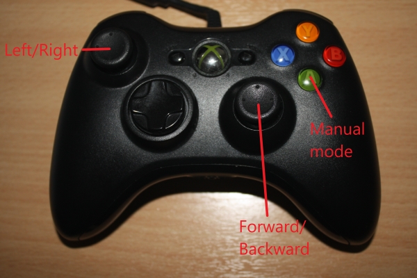
Building the ROS Packages on the Raspberry Pi (Robot Hardware)
To build and run the ROS packages on the Raspberry Pi for the robot hardware, follow these steps:
Create a catkin workspace:
$ mkdir -p ~/easerobot_ws/src
$ cd ~/easerobot_ws/
$ catkin_make
Copy the necessary packages:
Copy the following packages into the ~/easerobot_ws/src folder:
face_recognition
face_recognition_msgs
head_control
pan_tilt
easerobot
easerobot_missions
servo_msgs
speech
ros-keyboard (from ros-keyboard GitHub repository)
Build the code:
$ cd ~/easerobot_ws/
$ catkin_make
Ensure the build completes without any errors.
Compile and download the Arduino code:
You will need to compile and upload the Arduino code to the Nano to control the servos.
Train the face recognition software:
If not already done, follow the instructions in Part 2 to train the face recognition software.
Running the Code on the Robot
Launch the nodes on the robot:
With the Arduino connected to a USB port, use the launch file to start the nodes:
$ cd ~/easerobot_ws
$ source devel/setup.bash
$ roslaunch easerobot easerobot.launch
If no master node is running, this command will also launch roscore.
Start the keyboard node on the workstation:
On your Linux PC connected to the same network as the robot, run:
$ cd ~/test_ws
$ source devel/setup.bash
$ export ROS_MASTER_URI=http://ubiquityrobot:11311
$ rosrun keyboard keyboard
A window titled "ROS keyboard input" should appear.
Testing the Robot Hardware
Test 1: Running Mission 2
- Ensure the keyboard window has focus.
- Press the '2' key to start Mission 2.
The robot should begin moving its head/camera, scanning the room for known faces. After completing the scan, it will report either that no one was recognized or greet any recognized individuals.
Test 2: Manual Mode with Keyboard
- Ensure the keyboard window has focus.
- Press the 'm' key to enter manual mode.
- Use the cursor keys to move the head/camera.
- Press the 'd' key to return the head/camera to the default position.
Test 3: Manual Mode with Joystick Controller
Ensure the robot is stationary.
In a new terminal on the workstation, run:
$ cd ~/test_ws
$ source devel/setup.bash
$ export ROS_MASTER_URI=http://ubiquityrobot:11311
$ rosrun joystick joystick_node
A message indicating the node has started should appear.
With the configuration provided in the unchanged easerobot/config/config.yaml file and a wired Xbox 360 controller, you can control the robot head/camera movement using the joystick controls.
By following these steps, you can build and test the ROS packages on the Raspberry Pi, ensuring the robot hardware functions as expected and can be controlled remotely using a keyboard or joystick.
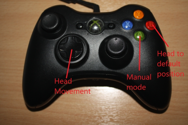
Testing Status Indication
To test the status indication of the robot, follow these steps:
Ensure the environment is set up correctly:
Open a terminal on your workstation and execute the following commands:
$ cd ~/test_ws
$ source devel/setup.bash
$ export ROS_MASTER_URI=http://ubiquityrobot:11311
Test Battery Status - Normal Level:
- Send a message to simulate a normal battery level:
$ rostopic pub -1 main_battery_status sensor_msgs/BatteryState '{voltage: 12}'
The status below the robot face should read "Battery level OK 12.00V".
Test Battery Status - Low Level:
Send a message to simulate a low battery level:
$ rostopic pub -1 main_battery_status sensor_msgs/BatteryState '{voltage: 9.4}'
The status below the robot face should read "9.40V".
Test Low Battery Warning:
Send the low battery message two more times to trigger the warning:
$ rostopic pub -1 main_battery_status sensor_msgs/BatteryState '{voltage: 9.4}'
$ rostopic pub -1 main_battery_status sensor_msgs/BatteryState '{voltage: 9.4}'
The status should read "Battery level low 9.40V".
The robot should speak a battery low warning.
The robot's facial expression should appear sad.
Test Suppression of Repeated Warnings:
Send the low battery message within 5 minutes of the last message:
$ rostopic pub -1 main_battery_status sensor_msgs/BatteryState '{voltage: 9.4}'
The warning should not be spoken again.
Test Repeated Warning After 5 Minutes:
Wait for 5 minutes and send the low battery message again:
$ rostopic pub -1 main_battery_status sensor_msgs/BatteryState '{voltage: 9.4}'
The spoken warning should be repeated.
Testing WAV File Playback
To test the functionality for WAV file playback, follow these steps:
- Ensure the robot is inactive: Ensure no commands are issued from either the keyboard or joystick node.
- Wait for 15 minutes: After issuing the last command, wait for 15 minutes.
- Observe WAV file playback: The robot should play a random WAV file.
The robot's mouth should animate along with the WAV file playback.
Debugging with rqt_graph
To aid debugging, you can use rqt_graph to visualize the current ROS system state: Install rqt_graph (if not already installed):
$ sudo apt-get install ros-<your_ros_distro>-rqt-graph
Replace
Run rqt_graph:
$ rqt_graph
A graphical representation of the ROS nodes and topics will be displayed.
You can use this to ensure all nodes and topics are connected as expected.
A full-size copy of the rqt_graph output image is included in the source zip file for further reference.
By following these steps, you can thoroughly test the status indication and WAV file playback functionalities of your robot.
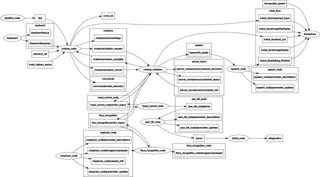
Summary
In this section, we've integrated code to regulate EaseRobot's actions, combining the code for Design Goals 1 and 2 to form Mission 2.
In our upcoming article, we'll fulfill Design Goal 3 by incorporating motors, a motor controller board, and software to operate the board. We'll also delve into the comprehensive EaseRobot hardware requirements, including circuit diagrams and a detailed list of necessary components.
Introduction
The EaseRobot Project is a hobbyist robotic project aimed at designing and building an autonomous house-bot using ROS (Robot Operating System). This article is the fifth in the series describing the project.
Background
In part 1, we defined the requirements for our robot by selecting our initial mission and breaking it down into several Design Goals to make it more manageable.
The mission was inspired by an article on building robots: "Let's build a robot!". The mission we chose was to enable the robot to recognize family members and act as a 'message taker and reminder'. For example, it could be instructed: "Robot, remind (PersonName) to pick me up from the station at 6pm". Even if the household member's phone is on silent or they are occupied, the robot could navigate the house, locate the person, and deliver the message.
The design goals identified for this mission are:
- Design Goal 1: Enable visual perception using a camera to detect faces and display messages for recognized individuals.
- Design Goal 2: Implement facial expression recognition and speech synthesis for effective communication.
- Design Goal 3: Implement locomotion control via remote keyboard and/or joystick.
- Design Goal 4: Integrate a laser range finder or similar sensor for navigation assistance.
- Design Goal 5: Achieve autonomous navigation capabilities.
- Design Goal 6: Implement task assignment and completion notification mechanisms.
Comparison: 2WD vs 4WD
In the early stages of developing EaseRobot, I initially envisioned it with four wheels and employing "Skid steering". Skid steering is advantageous for navigating rough terrain but consumes substantial power during turns. However, during initial trials, I noticed some unpredictability in turning behavior, likely due to the wide, knobby tires gripping tightly on the carpeted floor. Given that EaseRobot is designed for household use and doesn't require Mars-like terrain capabilities, I decided to simplify the design to two wheels and two passive casters, using "Differential drive". While simpler to implement, differential drive may not handle bumps and obstacles as effectively.
Initially, I used two furniture swivel casters for the passive wheels, but they didn't consistently align with the robot's intended direction, causing deviations from the desired path. Later on, I came across a 3D print design on Thingiverse that utilizes a table tennis ball as a caster. I customized this design by incorporating my own 3D printed spacer to adjust its height as needed. Despite lacking internal rollers found in commercial ball casters, this solution appears to meet EaseRobot's operational requirements effectively.
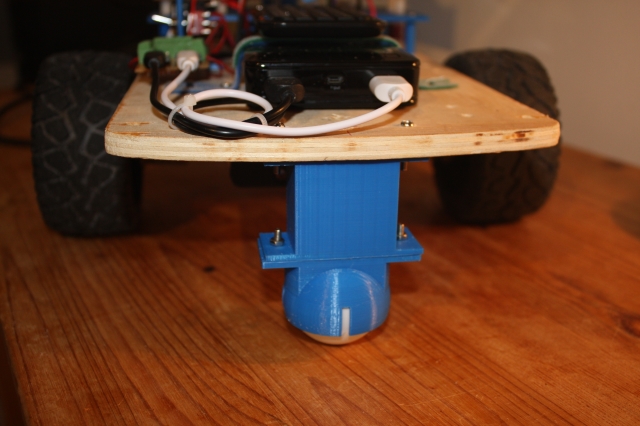
Motor Control Board Selection
The next critical decision in the design process was selecting a suitable control board to power the electric motors. Initially, I considered the L293D chip, as used in the PiRex project—a Raspberry Pi-based remote-controlled robot. Another option was the L298N motor driver board, known for its versatility. However, after careful evaluation, I opted for the Thunderborg from PiBorg. Despite being more expensive, this board offers higher power output and essential features such as under-voltage and short-circuit protection. Notably, it includes the capability to monitor battery voltage and features a safety mechanism that shuts down motors if communication with the controlling software is lost, preventing potential runaway scenarios.
Moreover, the Thunderborg integrates a 5V regulator, which will conveniently power the Raspberry Pi. Communication with the board utilizes an I2C link, facilitated by a library available for download from the PiBorg website. This library simplifies communication between the Raspberry Pi and Thunderborg, enabling straightforward motor control operations such as setting motor speeds with commands like TB.SetMotor1(0.5).
I will utilize the example code and library files provided in the PiBorg's zip package within my ROS node for seamless integration.
Geared Motors with Encoders
For the two electric motors, I have selected 12V geared motors equipped with a Hall effect sensor. These sensors will play a crucial role in our control strategy, particularly in implementing a PID controller to regulate the motor speed of each wheel. While the feedback from the Hall sensors is essential for PID functionality, their primary purpose will be to generate odometry data. This odometry information will be integrated with LIDAR data by the ROS navigation system, particularly when the robot operates in autonomous mode.
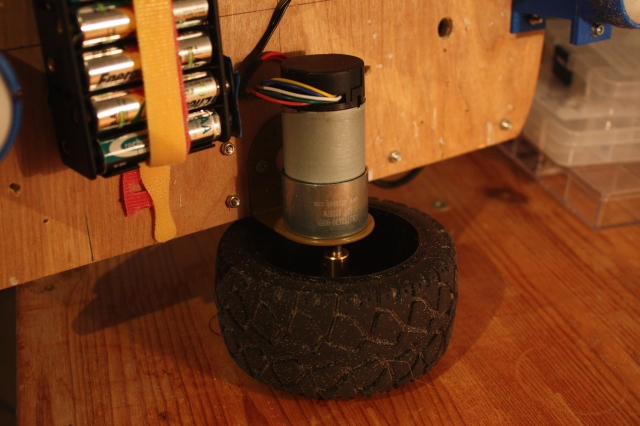
Code Development
In our next steps, we will focus on the code development for EaseRobot. This involves creating two new ROS packages and updating the existing easerobot package, particularly the Arduino sketch to handle signals from the Hall sensors.
tacho_msgs Package
The first new package, tacho_msgs, serves a straightforward purpose: defining a custom ROS message. This message will transmit RPM data from the Arduino node to the Raspberry Pi node controlling the motors. Here's an overview of the package structure:
- Package Structure:
tacho_msgs/msg/tacho.msg:float32 lwheelrpm # RPM of the left wheel float32 rwheelrpm # RPM of the right wheelThis message definition includes fields for the RPM of the left and right motors.launch/test.launch: Launches the serial node for communication with Arduino during initial package testing.
thunderborg Node Package
The second new package, thunderborg, will function as the driver node for the Thunderborg controller. Additionally, it will generate raw odometry messages. Here's a breakdown of this package:
- Package Structure:
thunderborg/cfg/thunderborg.cfg: A Python script used by the dynamic reconfiguration server to adjust PID parameters dynamically.Other standard ROS package files for node configuration and management.
These packages lay the foundation for integrating motor control, RPM feedback via custom messages, and dynamic PID tuning capabilities using the Thunderborg controller within the ROS framework.
#!/usr/bin/env python
# Dynamic rconfiguration for Thunderborg node
PACKAGE = "thunderborg"

from dynamic_reconfigure.parameter_generator_catkin import *

gen = ParameterGenerator()

gen.add("p_param", double_t, 0, "P-Proportional", 0.5, 0, 5)
gen.add("i_param", double_t, 0, "I-Integral", 0.9, 0, 5)
gen.add("d_param", double_t, 0, "D-Derivative", 0.006, 0, 5)

gen.add("restore_defaults", bool_t, 0, "Restore to original configuration", False)

exit(gen.generate(PACKAGE, "thunderborg_node", "Thunderborg"))
In the previous sections of this guide, we utilized the dynamic reconfiguration server. For the PID controller, the default parameters are initially set as follows: 0.5 for the proportional parameter, 0.9 for the integral parameter, and 0.006 for the derivative parameter. To fine-tune the PID controller, you can use the rqt_reconfiguration application. Once you have determined the optimal values, you should update them in the config.yaml file, which is detailed below.
Within the config folder, there exists a file named config.yaml. This specific file is referenced by the launch file to initialize the designated parameters on the parameter server. This approach allows for convenient system configuration adjustments without necessitating code recompilation.
p_param: 0.5
i_param: 0.9
d_param: 0.006

pid:
  use_pid: true
  inertia_level: 0.1

wheels:
  distance: 0.242
  circumference: 0.317

speed:
  # Plot x=thunderborg value, y=m/s
  slope: 0.649776
  y_intercept: -0.0788956
  motor_diag_msg: false
The config.yaml file includes the following parameters for configuration:
p_parm: Proportional parameter for the PID controlleri_parm: Integral parameter for the PID controllerd_parm: Derivative parameter for the PID controllerpid/use_pid: When set to true, enables the PID controller for motor speed controlpid/inertia_level: Sets a threshold motor speed value below which the robot does not movewheels/distance: Distance in meters between the two wheelswheels/circumference: Circumference of the wheels in metersspeed/slope: Slope value of the velocity-to-motor-controller-value conversion graphspeed/y_intercept: Y-intercept value of the velocity conversion graphspeed/motor_diag_msg: If true, publishes diagnostic messages for each motor for testing purposes
The ROS node is located in the src subfolder, specifically in the file thunderborg_node.py. This node utilizes a library file named ThunderBorg.py, which resides in src/thunderborg_lib. Both the node and the library are implemented in Python, following the conventions of the PiBorg website's code.
Here's an overview of the ROS node:
The main routine initializes ROS for the node and instantiates ThunderBorgNode. It then enters a loop that continues until the node is shut down. This loop operates at a frequency of 20Hz and invokes several functions from ThunderBorgNode, which are detailed below: - PublishStatus: Called at a rate of 1Hz. - PublishOdom and RunPIDs: Called during each iteration of the 20Hz loop.
def main(args):
    rospy.init_node('thunderborg_node', anonymous=False)
    rospy.loginfo("Thunderborg node started")
    tbn = ThunderBorgNode()

    rate = rospy.Rate(RATE)

    status_time = rospy.Time.now()

    while not rospy.is_shutdown():

        if rospy.Time.now() > status_time:
            tbn.PublishStatus()
            status_time = rospy.Time.now() + rospy.Duration(1)

        # Publish ODOM data
        tbn.PublishOdom()

        # Run the PIDs
        tbn.RunPIDs()

        rate.sleep()


if __name__ == '__main__':
    main(sys.argv)
The ThunderBorgNode class initializes upon reading values from the parameter server. Default values are used if any parameters are missing.
If the /pid/use_pid parameter is true, the constructor instantiates two instances of the PID controller (one for each motor) using the simple-pid library.
Next, an instance of the communication class with the Thunderborg board is created, and communication at the specified I2C address is verified.
Several variables are initialized, including topics for publishing battery status (main_battery_status), odometry data (raw_odom), and optionally, diagnostic messages for motor 1 and motor 2 (motor1_diag and motor2_diag).
The node subscribes to two topics: - cmd_vel: Published by the easerobot node from part 4, providing the required velocities for the robot. - tacho: Provides RPM (Revolutions Per Minute) for each motor.
class ThunderBorgNode:
    def __init__(self):
        self.__setup = False
        # Read values from parameter server
        # Using '~private_name' will prefix the parameters with the node name given in launch file
        self.__use_pid = rospy.get_param('~pid/use_pid', False)
        self.__wheel_distance = rospy.get_param('~wheels/distance', 0.23)
        self.__wheel_circumference = rospy.get_param('~wheels/circumference', 0.34)
        self.__speed_slope = rospy.get_param('~speed/slope', 1.5)
        self.__speed_y_intercept = rospy.get_param('~speed/y_intercept', 0.4)
        self.__inertia = rospy.get_param('~pid/inertia_level', 0.0)
        self.__diag_msgs = rospy.get_param('~speed/motor_diag_msg', False)

        pid_p = rospy.get_param('~p_param', 0.0)
        pid_i = rospy.get_param('~i_param', 0.0)
        pid_d = rospy.get_param('~d_param', 0.0)

        if self.__use_pid == True:
            # Configure the PIDs.
            self.__pid1 = PID(pid_p, pid_i, pid_d, setpoint=0)
            self.__pid1.sample_time = 0.05
            # Limit the pid range. The PID will only work in positive values
            self.__pid1.output_limits = (self.__inertia, 1.0)

            self.__pid2 = PID(pid_p, pid_i, pid_d, setpoint=0)
            self.__pid2.sample_time = 0.05
            self.__pid2.output_limits = (self.__inertia, 1.0)

            # We call dynamic server here after the PIDs are set up
            # so the new PID values are set after the PIDs were created
            srv = Server(ThunderborgConfig, self.DynamicCallback)

        self.__thunderborg = thunderborg_lib.ThunderBorg()  # create the thunderborg object
        self.__thunderborg.Init()
        if not self.__thunderborg.foundChip:
            rospy.logdebug("ThunderBorg board not found")
        else:
            # Setup board to turn off motors if we don't send a message every 1/4 second
            self.__thunderborg.SetCommsFailsafe(True)

        # Motor velocity feedback values m/s
        self.__feedback_velocity_right = 0.0
        self.__feedback_velocity_left = 0.0

        # Last motor direction
        self.__fwd_right = True
        self.__fwd_left = True

        # Speed request in m/s
        self.__speed_wish_right = 0.0
        self.__speed_wish_left = 0.0

        # Publish topics
        self.__status_pub = rospy.Publisher("main_battery_status", BatteryState, queue_size=1)
        self.__odom_pub = rospy.Publisher("raw_odom", Odometry, queue_size=50)
        if self.__diag_msgs == True:
            self.__diag1_pub = rospy.Publisher("motor1_diag", Vector3, queue_size=1)
            self.__diag2_pub = rospy.Publisher("motor2_diag", Vector3, queue_size=1)

        # ODOM values
        self.__odom_x = 0.0
        self.__odom_y = 0.0
        self.__odom_th = 0.0
        self.__last_odom_time = rospy.Time.now()

        # Subscribe to topics
        self.__vel_sub = rospy.Subscriber("cmd_vel",Twist, self.VelCallback)
        self.__feedback_sub = rospy.Subscriber("tacho", tacho, self.TachoCallback)
The function `DynamicCallbackis invoked during initialization and when PID parameters are modified. Its primary role is to update the PID parameters of two controllers based on dynamic reconfiguration. Upon the initial call, the current configuration is saved as the default setting. To revert to this default setup, users can click the "Restore to original configuration" checkbox on the reconfiguration server.
# Dynamic reconfiguration of PID settings
def DynamicCallback(self, config, level):
    # Store configuration on first call
    if not self.__setup:
        self.__default_config = config
        self.__setup = True
    else:
        # Restore configuration if requested
        if config.restore_defaults:
            config = self.__default_config
            config.restore_defaults = False

        # Update PID parameters
        self.__pid1.tunings = (config.p_param, config.i_param, config.d_param)
        self.__pid2.tunings = (config.p_param, config.i_param, config.d_param)

    return config
The MotorSetting function assists in converting a desired motor velocity from meters per second into a format compatible with the Thunderborg board (ranging from 0.0 to 1.0). This function employs a linear transformation based on slope and y-intercept values extracted from a configuration file to determine motor settings.
# Convert velocity to Thunderborg motor setting
def MotorSetting(self, vel):
    if vel == 0.0:
        setting = 0.0
    else:
        setting = (abs(vel) - self.__speed_y_intercept) / self.__speed_slope
        if vel < 0.0:
            setting = -setting
    return setting
The VelCallback function is triggered upon receiving messages on the cmd_vel topic, extracting linear and angular velocities. It calculates required speeds for both left and right motors, utilizing the MotorSetting function to derive Thunderborg board-compatible motor values. Depending on whether the PID controller is active, these motor values are either used directly to set the set point for the PID controllers or directly passed to the Thunderborg board when PID control is disabled. Diagnostic messages containing speed requirements, feedback velocities, and actual motor settings are published when enabled.
# Callback for cmd_vel message
def VelCallback(self, msg):
    # Calculate the requested speed of each wheel
    self.__speed_wish_right = ((msg.angular.z * self.__wheel_distance) / 2) + msg.linear.x
    self.__speed_wish_left = (msg.linear.x * 2) - self.__speed_wish_right

    # Convert speed demands to values understood by the Thunderborg.
    motor1_value = self.MotorSetting(self.__speed_wish_right)
    motor2_value = self.MotorSetting(self.__speed_wish_left)

    if self.__use_pid == True:
        # Using the PID so update set points
        self.__pid1.setpoint = abs(motor1_value)
        self.__pid2.setpoint = abs(motor2_value)

        if motor1_value == 0.0:
            # Leave flag as is
            pass
        elif motor1_value < 0.0:
            self.__fwd_right = False
        else:
            self.__fwd_right = True

        if motor2_value == 0.0:
            # Leave flag as is
            pass
        elif motor2_value < 0.0:
            self.__fwd_left = False
        else:
            self.__fwd_left = True

    else:
        # Update the Thunderborg directly
        self.__thunderborg.SetMotor1(motor1_value)
        self.__thunderborg.SetMotor2(motor2_value)

        if self.__diag_msgs == True:
            motor1_state = Vector3()
            motor1_state.x = self.__speed_wish_right
            motor1_state.y = self.__feedback_velocity_right
            motor1_state.z = motor1_value
            motor2_state = Vector3()
            motor2_state.x = self.__speed_wish_left
            motor2_state.y = self.__feedback_velocity_left
            motor2_state.z = motor2_value
            self.__diag1_pub.publish(motor1_state)
            self.__diag2_pub.publish(motor2_state)
The TachoCallback function is triggered whenever a message on the tacho topic is received, containing RPM values for each motor. This function converts these RPM values into meters per second (m/s) and stores them for future utilization.
# Callback for tacho message
def TachoCallback(self, msg):
    # Store the feedback values as velocity m/s
    self.__feedback_velocity_right = (msg.rwheelrpm/60.0)*self.__wheel_circumfrence
    self.__feedback_velocity_left = (msg.lwheelrpm/60.0)*self.__wheel_circumfrence
The PublishStatus function is invoked once per second from the main loop. It initializes a BatteryState message, retrieves the current battery voltage from the Thunderborg board, and assigns this value to the voltage element of the message. Subsequently, it publishes the message on the main_battery_status topic. This topic was detailed in part 4 of this article.
# Function to publish battery status message
def PublishStatus(self):
    # Create BatteryState message instance
    battery_msg = BatteryState()

    # Read current battery voltage from Thunderborg board
    battery_voltage = self.__thunderborg.get_battery_voltage()

    # Populate message with battery voltage
    battery_msg.voltage = battery_voltage

    # Publish battery status message
    self.__battery_status_pub.publish(battery_msg)
The RunPIDs function is executed during each iteration of the main loop. Its primary task involves interfacing with the PID controllers by passing current feedback values and receiving adjusted values as the PID systems move towards their set points. After obtaining these adjusted values, the function reintegrates the directional sign and proceeds to set motor speeds on the Thunderborg board accordingly. If diagnostic messaging is enabled, the function publishes diagnostic messages for each motor. These messages include the set point value, the PID controller output, and the current feedback from the motor.
# Update the PIDs and set the motor speeds
def RunPIDs(self):
    if self.__use_pid == True:
        # Update PIDs and get next value.
        if abs(self.__feedback_velocity_right) <= self.__inertia:
            pid1_output = self.__pid1(self.__inertia)
        else:
            pid1_output = self.__pid1(self.MotorSetting(abs(self.__feedback_velocity_right)))

        if abs(self.__feedback_velocity_left) <= self.__inertia:
            pid2_output = self.__pid2(self.__inertia)
        else:
            pid2_output = self.__pid2(self.MotorSetting(abs(self.__feedback_velocity_left)))

        if pid1_output <= self.__inertia:
            motor1_speed = 0.0
        elif self.__fwd_right == False:
            motor1_speed = -(pid1_output)
        else:
            motor1_speed = pid1_output

        if pid2_output <= self.__inertia:
            motor2_speed = 0.0
        elif self.__fwd_left == False:
            motor2_speed = -(pid2_output)
        else:
            motor2_speed = pid2_output

        # Set motor value
        self.__thunderborg.SetMotor1(motor1_speed)
        self.__thunderborg.SetMotor2(motor2_speed)

        if self.__diag_msgs == True:
            motor1_state = Vector3()
            motor1_state.x = self.__pid1.setpoint
            motor1_state.y = pid1_output
            motor1_state.z = self.__feedback_velocity_right
            motor2_state = Vector3()
            motor2_state.x = self.__pid2.setpoint
            motor2_state.y = pid2_output
            motor2_state.z = self.__feedback_velocity_left
            self.__diag1_pub.publish(motor1_state)
            self.__diag2_pub.publish(motor2_state)
The PublishOdom function is called during each iteration of the main loop. It calculates forward and angular velocities from feedback values of each motor. Using the elapsed time since the last call, it computes the distance moved in the x-direction and the rotation around the z-axis. These values are added to the odometry data. The rotation information is converted into Quaternion form using a helper function from the ROS transform package.
Subsequently, the function constructs an Odometry message, filling it with the computed odometry data and current velocities. This message is then published on the raw_odom topic. The raw_odom topic serves as input to generate an odom topic, crucial for ROS navigation system operations during manual mapping and autonomous navigation of the robot within the same location. It is important to note that additional data from a LIDAR sensor will be integrated for these navigational functionalities, which will be detailed in an upcoming article.
The process of utilizing the raw odometry data to generate the odometry data used by the navigation system will be detailed in a subsequent section of this article.
# Publish odometry data
    def PublishOdom(self):
        forward_velocity = (self.__feedback_velocity_left + self.__feedback_velocity_right)/2
        angular_velocity = 2*(self.__feedback_velocity_right - forward_velocity)/self.__wheel_distance

        # Now the x and y velocities
        velocity_x = forward_velocity
        velocity_y = 0.0

        # Note: As we don't receive velocity y we could remove all reference to it below, but
        # setting it to zero means we can keep the code generic below for future reference

        # Compute odometry from the calculate velocities
        current_time = rospy.Time.now()
        delta_time = (current_time - self.__last_odom_time).to_sec()    # Floating point seconds
        delta_x = (velocity_x * cos(self.__odom_th) - velocity_y * sin(self.__odom_th)) * delta_time
        delta_y = (velocity_x * sin(self.__odom_th) + velocity_y * cos(self.__odom_th)) * delta_time
        delta_th = angular_velocity * delta_time

        # Add the latest calculated movement
        self.__odom_x += delta_x
        self.__odom_y += delta_y
        self.__odom_th += delta_th

        # we need Yaw in a Quaternion
        odom_quat = quaternion_from_euler(0, 0, self.__odom_th)

        # Next publish the odometry message over ROS
        odom = Odometry()
        odom.header.stamp = current_time
        odom.header.frame_id = 'odom'

        odom.child_frame_id = 'base_footprint'

        odom.pose.pose = Pose(Point(self.__odom_x, self.__odom_y, 0.0), Quaternion(*odom_quat))
        odom.pose.covariance = [0.001, 0.0, 0.0, 0.0, 0.0, 0.0,
                                0.0, 0.001, 0.0, 0.0, 0.0, 0.0,
                                0.0, 0.0, 0.0, 0.0, 0.0, 0.0,
                                0.0, 0.0, 0.0, 0.0, 0.0, 0.0,
                                0.0, 0.0, 0.0, 0.0, 0.0, 0.0,
                                0.0, 0.0, 0.0, 0.0, 0.0, 0.001]

        odom.twist.twist = Twist(Vector3(velocity_x, velocity_y, 0), Vector3(0, 0, angular_velocity))

        odom.twist.covariance = [0.0001, 0.0, 0.0, 0.0, 0.0, 0.0,
                                 0.0, 0.0001, 0.0, 0.0, 0.0, 0.0,
                                 0.0, 0.0, 0.0, 0.0, 0.0, 0.0,
                                 0.0, 0.0, 0.0, 0.0, 0.0, 0.0,
                                 0.0, 0.0, 0.0, 0.0, 0.0, 0.0,
                                 0.0, 0.0, 0.0, 0.0, 0.0, 0.0001]

        # Publish the message
        self.__odom_pub.publish(odom)

        self.__last_odom_time = current_time
In the src folder, there exists a non-ROS Python script named test.py. This script will be utilized in a test scenario to compute the slope and y-intercept of the graph used for converting wheel velocity to motor speed settings. The specific purpose and usage of this file will be elaborated upon in a subsequent section of this article.
#!/usr/bin/env python
import thunderborg_lib
import time

# Run with different values 0.1, 0.2, 0.3, 0.4, 0.5, 0.6, 0.7, 0.8, 0.9, 1.0
# WARNING ensure your robot has room to run for 5 seconds at the set speed or change the sleep time!
speed = 0.5

TB = thunderborg_lib.ThunderBorg()  # create the thunderborg object
TB.Init()

if not TB.foundChip:
    print("ThunderBorg board not found")
else:
    # Set both motor speeds
    TB.SetMotor1(speed)
    TB.SetMotor2(speed)

    time.sleep(5)

    TB.SetMotor1(0.0)
    TB.SetMotor2(0.0)
Odometry Data
To enhance the accuracy of odometry data, we can integrate it with data from an IMU (Inertial Measurement Unit) using a Kalman Extended Filter. While the IMU integration will be addressed in future implementations, we will initially incorporate a ROS Kalman Extended Filter node to prepare for IMU integration. This node will continue to publish odometry data despite the absence of IMU input and will broadcast odometry transformation data. Further details on transformations can be found on the ROS Wiki.
For this purpose, we will employ the robot_localization package. Documentation for this package can be accessed here.
In the easerobot/config folder, I've included a robot_localization.yaml configuration file for the node. This file specifies that we are configuring a 2D planner robot, defines which message data should be utilized, and indicates our intent to broadcast tf data.
frequency: 40
sensor_timeout: 1
two_d_mode: true

publish_tf: true

print_diagnostics: false    # Set to true for debug

odom_frame: odom
base_link_frame: base_footprint
world_frame: odom

odom0: /raw_odom
imu0: /imu/data

odom0_config: [false, false, false,
               false, false, false,
               true,  true,  false,
               false, false, true,
               false, false, false]

odom0_differential: false

imu0_config: [false, false, false,
              false, false, false,
              false, false, false,
              false, false, true,
              false, false, false]


imu0_differential: false

odom0_relative: false
imu0_relative: true

process_noise_covariance": [0.05, 0,    0,    0,    0,    0,    0,     0,     0,    0,    0,    0,    0,    0,    0,
                            0,    0.05, 0,    0,    0,    0,    0,     0,     0,    0,    0,    0,    0,    0,    0,
                            0,    0,    0.06, 0,    0,    0,    0,     0,     0,    0,    0,    0,    0,    0,    0,
                            0,    0,    0,    0.03, 0,    0,    0,     0,     0,    0,    0,    0,    0,    0,    0,
                            0,    0,    0,    0,    0.03, 0,    0,     0,     0,    0,    0,    0,    0,    0,    0,
                            0,    0,    0,    0,    0,    0.06, 0,     0,     0,    0,    0,    0,    0,    0,    0,
                            0,    0,    0,    0,    0,    0,    0.025, 0,     0,    0,    0,    0,    0,    0,    0,
                            0,    0,    0,    0,    0,    0,    0,     0.025, 0,    0,    0,    0,    0,    0,    0,
                            0,    0,    0,    0,    0,    0,    0,     0,     0.04, 0,    0,    0,    0,    0,    0,
                            0,    0,    0,    0,    0,    0,    0,     0,     0,    0.01, 0,    0,    0,    0,    0,
                            0,    0,    0,    0,    0,    0,    0,     0,     0,    0,    0.01, 0,    0,    0,    0,
                            0,    0,    0,    0,    0,    0,    0,     0,     0,    0,    0,    0.02, 0,    0,    0,
                            0,    0,    0,    0,    0,    0,    0,     0,     0,    0,    0,    0,    0.01, 0,    0,
                            0,    0,    0,    0,    0,    0,    0,     0,     0,    0,    0,    0,    0,    0.01, 0,
                            0,    0,    0,    0,    0,    0,    0,     0,     0,    0,    0,    0,    0,    0,    0.015]

initial_estimate_covariance: [1e-9, 0,    0,    0,    0,    0,    0,     0,     0,    0,    0,    0,    0,    0,    0,
                              0,    1e-9, 0,    0,    0,    0,    0,     0,     0,    0,    0,    0,    0,    0,    0,
                              0,    0,    1e-9, 0,    0,    0,    0,     0,     0,    0,    0,    0,    0,    0,    0,
                              0,    0,    0,    1e-9, 0,    0,    0,     0,     0,    0,    0,    0,    0,    0,    0,
                              0,    0,    0,    0,    1e-9, 0,    0,     0,     0,    0,    0,    0,    0,    0,    0,
                              0,    0,    0,    0,    0,    1e-9, 0,     0,     0,    0,    0,    0,    0,    0,    0,
                              0,    0,    0,    0,    0,    0,    1e-9,  0,     0,    0,    0,    0,    0,    0,    0,
                              0,    0,    0,    0,    0,    0,    0,     1e-9,  0,    0,    0,    0,    0,    0,    0,
                              0,    0,    0,    0,    0,    0,    0,     0,     1e-9, 0,    0,    0,    0,    0,    0,
                              0,    0,    0,    0,    0,    0,    0,     0,     0,    1e-9, 0,    0,    0,    0,    0,
                              0,    0,    0,    0,    0,    0,    0,     0,     0,    0,    1e-9, 0,    0,    0,    0,
                              0,    0,    0,    0,    0,    0,    0,     0,     0,    0,    0,    1e-9, 0,    0,    0,
                              0,    0,    0,    0,    0,    0,    0,     0,     0,    0,    0,    0,    1e-9, 0,    0,
                              0,    0,    0,    0,    0,    0,    0,     0,     0,    0,    0,    0,    0,    1e-9, 0,
                              0,    0,    0,    0,    0,    0,    0,     0,     0,    0,    0,    0,    0,    0,    1e-9]
To set up the ROS nodes for integrating odometry data with the Kalman Extended Filter using the robot_localization package, we'll modify the easerobot.launch file as follows:
<node pkg="tf2_ros" type="static_transform_publisher" name="base_footprint_broadcaster" args="0 0 0.09 0 0 0 /base_footprint /base_link"/>

<node pkg="robot_localization" type="ekf_localization_node" name="ekf_localization_node">
  <remap from="odometry/filtered" to="odom"/>
  <rosparam command="load" file="$(find easerobot)/config/robot_localization.yaml"/>
</node>
- The first
block creates a node using tf2_ros to broadcast a static transform between the base_footprint frame and the base_link frame. This transformation is necessary for the operation of the ekf_localization_node. - The second
block initializes the ekf_localization_node from the robot_localization package. It remaps the output topic from odometry/filtered to odom, aligning it with standard ROS conventions. Additionally, it loads the configuration parameters from the robot_localization.yaml file located in the easerobot/config directory.
This setup prepares the ROS environment to fuse odometry data with future IMU data using a Kalman Extended Filter, improving overall localization accuracy.
Updates to the EaseRobot Node Package
In the previous section, we introduced the easerobot and easerobot_missions nodes. As development progresses with EaseRobot, it's crucial to enhance the functionality of these nodes. Here, we will focus on updates to the easerobot package.
The primary update involves modifying the sketch running on the Arduino Nano board. Currently, the sketch subscribes to the servo topic to control the pan-tilt device. We will extend its functionality to monitor the Hall effect sensors of each motor and publish RPM data via the tacho topic.
Each Hall sensor produces two outputs, A and B, which pulse as the motor rotates. These outputs can be monitored by the Arduino to detect speed and direction. Output A will be connected to an interrupt on the Arduino, while output B will be connected to a digital input.
In the setup function of the sketch, we will configure the B pins as inputs and attach the A pins to interrupt 0 and 1.
Two interrupt service routines, WheelSpeed0 and WheelSpeed1, will be implemented to count the pulses received and determine the motor direction based on the relationship between pins A and B.
Within the loop function, every 50ms, we will calculate the RPM values for each motor based on the pulse counts, reset the counts, and publish the RPM values on the tacho topic.
/*
 * This version controls upto four RC Servos and publishes the tacho message monitoring
 * two motors.
 *
 * The node subscribes to the servo topic and acts on a easerobot_msgs::servo_array message.
 * This message contains two elements, index and angle. Index references the servos 0-3 and
 * angle is the angle to set the servo to 0-180.
 *
 * D2 -> INT0 used for monitoring right motor speed
 * D3 -> INT1 used for monitoring left motor speed
 * D4 -> Digital input used for sensing right motor direction
 * D5 -> PWM servo indexed 2
 * D6 -> PWM servo indexed 1
 * D7 -> Digital input used for sensing left motor direction
 * D9 -> PWM servo indexed 0
 * D10 -> PWM servo indexed 3
 */

#if (ARDUINO >= 100)
 #include <Arduino.h>
#else
 #include <WProgram.h>
#endif

#include <Servo.h>
#include <ros.h>
#include <servo_msgs/servo_array.h>
#include <tacho_msgs/tacho.h>

// Define the PWM pins that the servos are connected to
#define SERVO_0 9
#define SERVO_1 6
#define SERVO_2 5
#define SERVO_3 10

// Define pins used for two Hall sensors
#define ENCODER0_PINA 2 // Interrupt 0
#define ENCODER0_PINB 4
#define ENCODER1_PINA 3 // Interrupt 1
#define ENCODER1_PINB 7

#define GEAR_BOX_COUNTS_PER_REV 1440.0f

ros::NodeHandle  nh;

Servo servo0;
Servo servo1;
Servo servo2;
Servo servo3;

tacho_msgs::tacho tachoMsg;

byte encoder0PinALast;
byte encoder1PinALast;
volatile int encoder0Count; // Number of pulses
volatile int encoder1Count; // Number of pulses
volatile boolean encoder0Direction; //Rotation direction
volatile boolean encoder1Direction; //Rotation direction

void servo_cb( const servo_msgs::servo_array& cmd_msg)
{
  /* Which servo to drive */
  switch(cmd_msg.index)
  {
    case 0:
      nh.logdebug("Servo 0 ");
      servo0.write(cmd_msg.angle); //set servo 0 angle, should be from 0-180
      break;

    case 1:
      nh.logdebug("Servo 1 ");
      servo1.write(cmd_msg.angle); //set servo 1 angle, should be from 0-180
      break;

    case 2:
      nh.logdebug("Servo 2 ");
      servo2.write(cmd_msg.angle); //set servo 2 angle, should be from 0-180
      break;

    case 3:
      nh.logdebug("Servo 3 ");
      servo3.write(cmd_msg.angle); //set servo 3 angle, should be from 0-180
      break;

    default:
      nh.logdebug("No Servo");
      break;
  }
}

ros::Subscriber<servo_msgs::servo_array> sub("servo", servo_cb);
ros::Publisher pub("tacho", &tachoMsg);

void setup()
{
  nh.initNode();
  nh.subscribe(sub);
  nh.advertise(pub);

  servo0.attach(SERVO_0); //attach it to the pin
  servo1.attach(SERVO_1);
  servo2.attach(SERVO_2);
  servo3.attach(SERVO_3);

  encoder0Direction = true;   // default is forward
  encoder1Direction = true;
  encoder0Count = 0;
  encoder1Count = 0;

  pinMode(ENCODER0_PINB, INPUT);
  pinMode(ENCODER1_PINB, INPUT);

  // Attach the interrupts for the Hall sensors
  attachInterrupt(0, WheelSpeed0, CHANGE); // Int0 is pin 2
  attachInterrupt(1, WheelSpeed1, CHANGE); // Int1 is pin 3

  // Defaults
  servo0.write(90);
  servo1.write(120);
}

unsigned long publisherTime;
unsigned long currentTime;
unsigned long lastTime;
float deltaTime;

void loop()
{
  // Is it time to publish the tacho message
  if(millis() > publisherTime)
  {
    currentTime = micros();
    deltaTime = (float)(currentTime - lastTime)/1000000.0;

    // Right wheel speed
    tachoMsg.rwheelrpm = (((((float)encoder0Count)/2.0f)/deltaTime)/GEAR_BOX_COUNTS_PER_REV)*60.0f;
    encoder0Count = 0;

    // Left wheel speed
    tachoMsg.lwheelrpm = (((((float)encoder1Count)/2.0f)/deltaTime)/GEAR_BOX_COUNTS_PER_REV)*60.0f;
    encoder1Count = 0;

    lastTime = currentTime;

    pub.publish(&tachoMsg);
    publisherTime = millis() + 50; // Publish at 20Hz
  }

  nh.spinOnce();
}

// ISR 0
void WheelSpeed0()
{
  int state = digitalRead(ENCODER0_PINA);

  if((encoder0PinALast == LOW) && (state == HIGH))
  {
    int val = digitalRead(ENCODER0_PINB);

    if(val == LOW && encoder0Direction)
    {
      encoder0Direction = false; // Reverse
    }
    else if (val == HIGH && !encoder0Direction)
    {
      encoder0Direction = true; // Forward
    }
  }

  encoder0PinALast = state;

  if(!encoder0Direction)
  {
    encoder0Count++;
  }
  else
  {
    encoder0Count--;
  }
}

// ISR 1
void WheelSpeed1()
{
  int state = digitalRead(ENCODER1_PINA);

  if((encoder1PinALast == LOW) && (state == HIGH))
  {
    int val = digitalRead(ENCODER1_PINB);

    if(val == LOW && encoder1Direction)
    {
      encoder1Direction = false; // Reverse
    }
    else if (val == HIGH && !encoder1Direction)
    {
      encoder1Direction = true; // Forward
    }
  }

  encoder1PinALast = state;

  if(!encoder1Direction)
  {
    encoder1Count++;
  }
  else
  {
    encoder1Count--;
  }
}
Further updates have been implemented in the easerobot_node.cpp file within the EaseRobot node codebase.
One significant enhancement involves motor speed ramping to a target value. This adjustment aims to prevent skidding and shuddering that can occur when attempting abrupt velocity changes. With the integration of a PID controller, velocity changes are now managed in a controlled manner. Thus, if the PID controller is enabled, the ramp functionality in the EaseRobot node becomes unnecessary.
In the constructor of the EaseRobotNode class, the following line has been added to retrieve the PID controller's enablement status from the parameter server:
nh_.param("/thunderborg_node/pid/use_pid", pid_enabled_, false);
This addition ensures that the EaseRobotNode class adapts its behavior based on whether the PID controller functionality is enabled or not.
void EaseRobotNode::sendTwist(void)
{
    geometry_msgs::Twist target_twist;

    // If in manual locomotion mode use keyboard or joystick data
    if(manual_locomotion_mode_ == true)
    {
        // Publish message based on keyboard or joystick speeds
        if((keyboard_linear_speed_ == 0) && (keyboard_angular_speed_ == 0))
        {
            // Use joystick values
            target_twist.linear.x = joystick_linear_speed_;
            target_twist.angular.z = joystick_angular_speed_;
        }
        else
        {
            // use keyboard values
            target_twist.linear.x = keyboard_linear_speed_;
            target_twist.angular.z = keyboard_angular_speed_;
        }
    }
    else
    {
        // Use mission demands (autonomous)
        target_twist.linear.x = linear_mission_demand_;
        target_twist.angular.z = angular_mission_demand_;
    }

    // If not using the PID ramp to the target value.
    if (false == pid_enabled_)
    {
        ros::Time time_now = ros::Time::now();

        // Ramp towards are required twist velocities
        last_twist_ = rampedTwist(last_twist_, target_twist, last_twist_send_time_, time_now);

        last_twist_send_time_ = time_now;

        // Publish the Twist message using the ramp value
        twist_pub_.publish(last_twist_);
    }
    else
    {
        // Publish the Twist message using the target value
        twist_pub_.publish(target_twist);
    }
}
Continuing with enhancements in the easerobot_node.cpp file within the EaseRobot node codebase, another notable improvement addresses the response to joystick input during robot movement control.
Previously, joystick input values within the dead zone were ignored, and values outside this zone were scaled using a basic linear transformation. This approach occasionally led to incorrect mapping of joystick values to lower speeds immediately above the dead zone. To rectify this, we've implemented a more nuanced mapping strategy using straight-line graphs. The slope and y-intercept for these graphs are now dynamically calculated based on the specified dead zone values.
In the constructor of the EaseRobotNode class, the following code snippet has been added to compute the slope and y-intercept for both linear and angular velocity graphs.
These calculations ensure that joystick input is accurately translated into corresponding linear and angular velocities, providing smoother and more responsive control of the robot's movement.
// Calculate the slope and y-intercept of the joytick input against linear speed
lslope_ = max_linear_speed_/(MAX_AXES_VALUE_-dead_zone_);
lyintercept_ = -(lslope_*dead_zone_);

// Calculate the slope and y-intercept of the joytick input against angular speed
aslope_ = max_angular_speed_/(MAX_AXES_VALUE_-dead_zone_);
ayintercept_ = -(aslope_*dead_zone_);
To integrate the calculated slopes and y-intercepts into the joystickCallback function for precise speed calculation based on joystick input, follow this approach:
void EaseRobotNode::joystickCallback(const sensor_msgs::Joy::ConstPtr& msg)
{
    float joystick_x_axes;
    float joystick_y_axes;

    // manual locomotion mode can use the joystick/game pad
    joystick_x_axes = msg->axes[angular_speed_index_];
    joystick_y_axes = msg->axes[linear_speed_index_];

    // Check for manual movement

    // Check dead zone values
    if(abs(joystick_y_axes) < dead_zone_)
    {
        joystick_linear_speed_ = 0.0f;
    }
    else
    {
        joystick_linear_speed_ = (lslope_*(float)abs(joystick_y_axes))+lyintercept_;

        if(joystick_y_axes > 0.0f)
        {
            joystick_linear_speed_ = -joystick_linear_speed_;
        }
    }

    // Check dead zone values
    if(abs(joystick_x_axes) < dead_zone_)
    {
        joystick_angular_speed_ = 0.0f;
    }
    else
    {
        joystick_angular_speed_ = (aslope_*(float)abs(joystick_x_axes))+ayintercept_;

        if(joystick_x_axes > 0.0f)
        {
            joystick_angular_speed_ = -joystick_angular_speed_;
        }
    }
...
To incorporate the thunderborg configuration loading and node launching adjustments into the easerobot.launch file, you can add the following XML snippet:
<!-- Load ThunderBorg configuration and start thunderborg_node -->
<node pkg="thunderborg" type="thunderborg_node.py" name="thunderborg_node" output="screen">
  <rosparam command="load" file="$(find thunderborg)/config/config.yaml"/>
</node>
Using the Code
I will execute the code on the robot hardware and run the joystick node along with test applications on a Linux PC, referred to as the workstation in the following details. Alternatively, you can connect the joystick directly to the robot and run the joystick node on the robot hardware. Additionally, I will demonstrate how to utilize the test.py script to compute slope and y-intercept values for configuring the thunderborg in the config.yaml file.
Building the ROS Packages on the Pi (Robot Hardware)
If not already completed, establish a catkin workspace on the Raspberry Pi and initialize it using the commands below:
$ mkdir -p ~/easerobot_ws/src
$ cd ~/easerobot_ws/
$ catkin_make
Next, copy the following packages: face_recognition, face_recognition_msgs, head_control, pan_tilt, easerobot, easerobot_missions, servo_msgs, speech, thunderborg, tacho_msgs, and ros-keyboard (available at ros-keyboard) into the ~/easerobot_ws/src directory.
Navigate to the easerobot_ws directory and build the code using the commands provided:
$ cd ~/easerobot_ws/
$ catkin_make
Ensure that the build completes successfully without encountering any errors.
Compiling and Downloading Arduino Code to Nano
Additionally, compile and download the Arduino code to the Nano.
Building the ROS Packages on the Workstation
To operate the keyboard and joystick nodes on the workstation for remote control of the robot hardware, follow these steps to create a workspace:
$ mkdir -p ~/test_ws/src
$ cd ~/test_ws/
$ catkin_make
Next, copy the following packages: easerobot, joystick, odom_test (from the Robotics-test-code folder), and ros-keyboard (available at ros-keyboard) into the ~/test_ws/src directory. Then, proceed to build the code with the following commands:
$ cd ~/test_ws/
$ catkin_make
Verify that the build completes successfully without any errors.
Tip: Simplifying ROS Commands
To streamline the process of running ROS code and tools on both the Raspberry Pi and workstation, consider these tips to minimize repetitive typing:
For Raspberry Pi:
- Automate Setup Script in .bashrc: Open the .bashrc file using nano:
$ cd ~/
$ nano .bashrc
Add the following line at the end of the file:
source /home/ubuntu/easerobot_ws/devel/setup.bash
Save and exit. Now, whenever you open a new terminal on the Raspberry Pi, the setup script will be sourced automatically.
For Workstation:
- Create Alias in .bashrc: Edit the .bashrc file for the workstation:
$ nano ~/.bashrc
Add the following alias:
alias easerobot='source ~/test_ws/devel/setup.bash; export ROS_MASTER_URI=http://ubiquityrobot:11311'
Save and exit. Now, you can simply type easerobot in a terminal to execute both commands, saving typing effort.
Utilize TAB Completion:
Take advantage of TAB completion in ROS tools. For instance, when typing commands like:
$ rosrun rosserial_
Pressing TAB after typing rosserial_ will auto-complete trosserial_python`, reducing manual typing.
The Hardware
In the course of this article, various hardware additions have been detailed without providing a comprehensive list of all components used. Here, a complete bill of materials for the project is now accessible.
Looking forward, when integrating the LIDAR, control will transition to the Arduino, utilizing ROS messages generated by it, thereby reducing the Raspberry Pi's role. Given current memory constraints on the Arduino Nano, options include adding a second Nano or upgrading to a Teensy, which is compatible with existing Arduino code with the aid of a plugin for the Arduino IDE. Note, however, that some Teensy models are not tolerant to 5V signals, necessitating level adjustments.
In the initial part of this guide, reference was made to the Ubiquity Robot Image utilized on the Raspberry Pi. Detailed instructions on image installation, additional software setup, and project-specific configuration are available here.
A full-scale circuit diagram is included in the diagrams zip folder, alongside an rqt_graph image illustrating all nodes and topics.
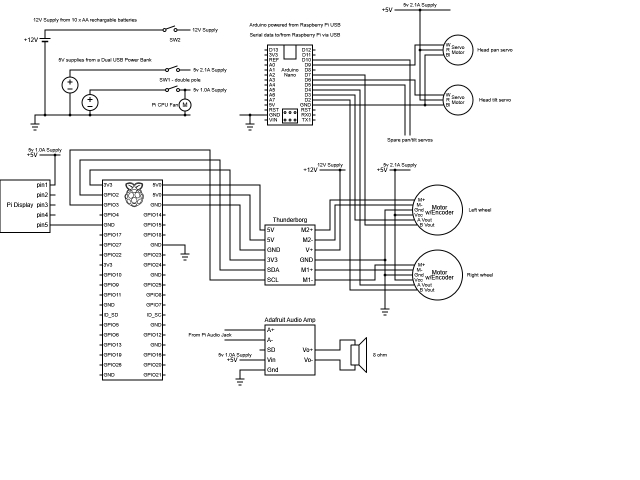
The circuit diagram shows that the Thunderborg board and motors are powered by 10 AA batteries, supplying 5V to the Raspberry Pi via the Thunderborg. The Nano is powered by the Raspberry Pi. Additionally, a USB power pack provides two distinct 5V rails: a 2.1A output for RC servos and motor hall sensors, and a 1.0A output for the display, audio amplifier, and CPU fan.
For the motors, the power and A/B signals from the right-hand motor's hall sensor are swapped compared to the left-hand motor, standardizing motor control and sensor feedback directions.
EaseRobot is currently under construction.
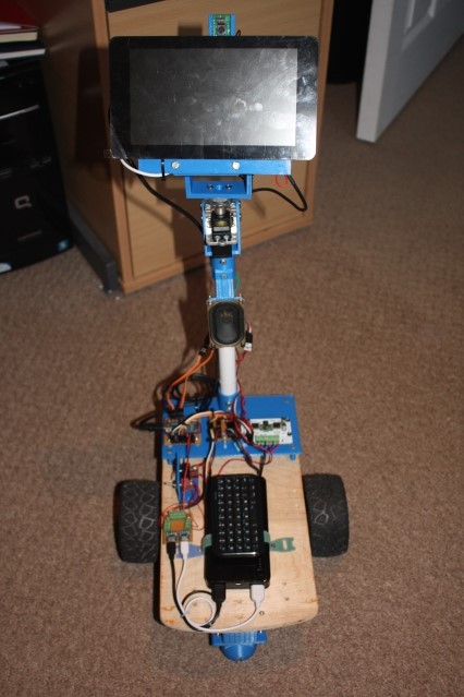
Two Micro USB breakout boards connect the USB power pack outputs.
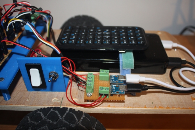
EaseRobot's base includes a stowed mini Bluetooth keyboard, secured with Velcro, for easy Raspberry Pi interface during testing.
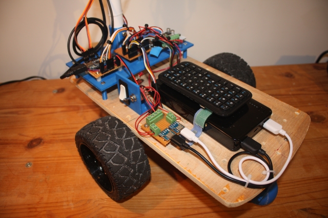
The rear platform houses the Arduino Nano, Thunderborg, and connection board.
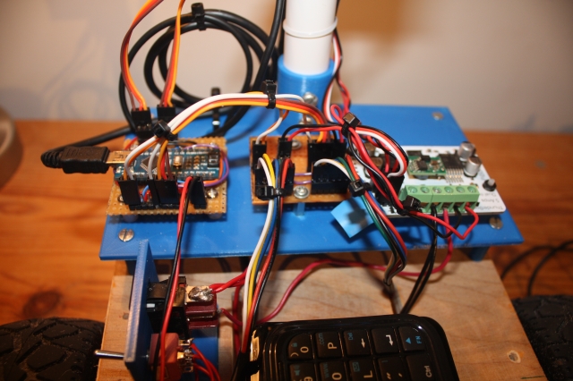
The display's rear view shows the Raspberry Pi, camera setup, and Vero board with the audio amplifier, also serving as an I2C junction for connections to the Thunderborg.
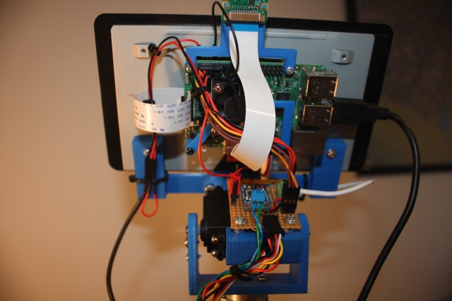
As a prototype, EaseRobot is subject to design revisions. Future plans include replacing the flexible plastic pipe used for the head with a more rigid material, potentially wood or a sturdy dowel. The rectangular robot base, initially designed for four wheels, may be reconfigured into a round design to accommodate its current two-wheel setup. Additionally, future upgrades aim to consolidate power sources into a single rechargeable battery, allowing autonomous recharging at a docking station. However, immediate focus remains on achieving full autonomy.
Summary
This section marks the completion of Design Goal 3, achieving locomotion control through a remote keyboard and/or joystick. Additionally, comprehensive circuit diagrams and a bill of materials have been compiled for the current build.
Next steps include integrating a laser range finder to fulfill Design Goal 4, enhancing EaseRobot's capabilities. Furthermore, an IMU will be incorporated to refine odometry performance.
Introduction
The EaseRobot project aims to create an autonomous house-bot using the Robot Operating System (ROS). This article marks the sixth installment in our ongoing series documenting this project.
Background
In the initial installment, we outlined our mission and broke it down into several design goals to manage the complexity.
The mission, inspired by the article "Let's Build a Robot!", was to create a robot that could relay messages within a household. The concept involved the robot recognizing family members and delivering messages, such as reminders to pick someone up from a station at a specific time.
The design goals were as follows:
- Enable the robot to use a camera to search for faces, identify people, and display messages.
- Incorporate facial expression recognition and speech synthesis for message delivery.
- Implement remote control locomotion via a keyboard or joystick.
- Add a laser range finder or similar sensor to assist with navigation.
- Achieve autonomous movement.
- Develop a system for task assignment and completion notifications.
In the previous segment, we achieved motor control and odometry feedback, fulfilling Design Goal 3. This segment focuses on integrating a spinning LIDAR (Light Detection and Ranging) to achieve Design Goal 4 and enhancing odometry with an Inertial Measurement Unit (IMU). Additionally, we'll replace the Arduino Nano with a Teensy 3.5.
Adding a LIDAR
Autonomous navigation in ROS typically involves subscribing to the /scan and /tf topics. The /tf topic provides the odom transform, which we started broadcasting in the previous segment using the ekf_localization_node. The /scan topic contains data from a laser scanning device.
High-end 360-degree LIDAR systems are used in autonomous vehicles, but for our indoor robot, a more affordable option like the Slamtec RPLidar A1 is suitable. Priced around £100 (GBP), this device offers a 12-meter range, 360-degree scan, and communicates via a serial interface. Moreover, Slamtec provides a ROS node available on their GitHub, allowing us to easily integrate the RPLidar with our robot.
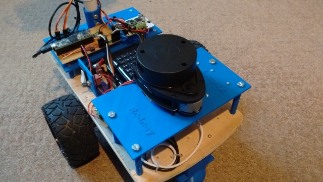
I purchased the RPLidar Development Kit, which includes a USB serial device and cable for connection. The device supplies 5V to both the LIDAR motor and core and features a PWM input to control motor speed. To balance power distribution, I chose to supply power to the motor and core separately, using a simple breakout board. The USB serial device is powered by the Raspberry Pi via USB.
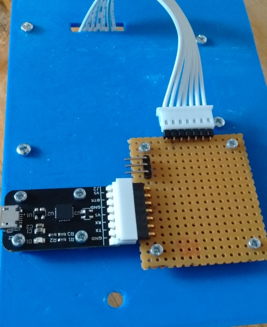
For those following from the beginning, you might notice an issue: the robot's neck obstructs the LIDAR's laser, causing constant detection in its 360-degree field. To address this, we'll use the LaserScanAngularBoundsFilter from the ROS laser_filters package to exclude the neck area by filtering out 10 degrees on either side of the 180-degree mark.
Configuring the LIDAR
We'll modify the rodney and rodney_missions packages from previous segments to include the RPLidar. The laser_filter node will be launched from our rodney.launch file, requiring a configuration file loaded into the ROS parameter server.
Create laser_filter_config.yaml in the rodney/config folder with the following content:
scan_filter_chain:
- name: angle
  type: laser_filters/LaserScanAngularBoundsFilter
  params:
    lower_angle: -2.96706
    upper_angle: 2.96706
The angles are in radians, limiting the field of view to 0 to -170 and 0 to +170 degrees.
Next, add the following to rodney.launch in the rodney/launch folder:
<node pkg="laser_filters" type="scan_to_scan_filter_chain" name="scan_to_scan_filter_chain" output="screen">
  <rosparam command="load" file="$(find rodney)/config/laser_filter_config.yaml"/>
  <remap from="scan" to="scan_filter_input"/>
  <remap from="scan_filtered" to="scan"/>
</node>
This remaps the output topic of the node from scan_filtered to scan.
Launching the RPLidar Node
To launch the RPLidar node, we need to handle the device identification. Linux identifies the serial device as /dev/ttyUSBn, which can be ambiguous if multiple devices are connected. We resolve this by creating udev rules to set symbolic links.
Create rodney_udev.rules in the rodney/scripts folder:
# Set the udev rules.
#
# Arduino Nano
KERNEL=="ttyUSB*", ATTRS{idVendor}=="1a86", ATTRS{idProduct}=="7523", MODE:="0777", SYMLINK+="nano"
#
# Teensy
KERNEL=="ttyACM*", ATTRS{idVendor}=="16c0", ATTRS{idProduct}=="0483", MODE:="0777", SYMLINK+="teensy"
#
# RPLidar
KERNEL=="ttyUSB*", ATTRS{idVendor}=="10c4", ATTRS{idProduct}=="ea60", MODE:="0777", SYMLINK+="rplidar"
Copy this file to the /etc/udev/rules.d folder on the Raspberry Pi using a sudo command or the provided create_udev_rules.sh script.
Add the command to launch the RPLidar node to rodney.launch:
<node pkg="rplidar_ros" type="rplidarNode" name="rplidar_node" output="screen">
  <param name="serial_port" type="string" value="/dev/rplidar"/>
  <param name="serial_baudrate" type="int" value="115200"/>
  <param name="frame_id" type="string" value="laser"/>
  <remap from="scan" to="scan_filter_input"/>
</node>
We'll build and run the code in the "Using the Code" section later, but the image below shows the laser scan message visualized in rviz.
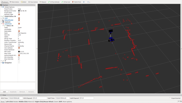
Integrating an Inertial Measurement Unit (IMU)
Background
In part 5, we began broadcasting raw odometry data derived from the motor encoders and introduced the ekf_localization_node, which we planned to use for fusing raw odometry with IMU data to enhance the robot's odometry accuracy.
For this segment, we'll integrate a SparkFun MPU-9250 breakout board as our IMU.
Connecting the IMU
Instead of connecting the IMU directly to the Raspberry Pi, we'll link it to the microcontroller. Given that the Arduino Nano's memory is nearly maxed out, we need a more robust solution. We could either add a second Nano or switch to a larger Arduino board. However, I've decided to replace the Nano with a Teensy 3.5. The Teensy 3.5 is not only faster and has more memory than an Arduino but is also compatible with Arduino software and libraries. You can use a plugin to continue developing with the Arduino IDE. I chose the Teensy 3.5 because, unlike the Teensy 3.6, its digital inputs are 5V tolerant.
Below is an image showing the IMU (MPU-9250 breakout board) at the bottom and the Teensy at the top left.
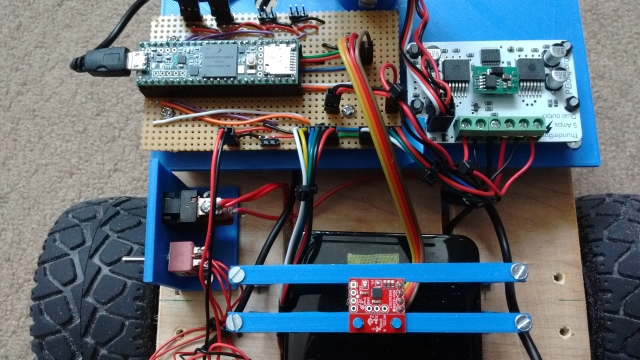
Updating the Arduino Sketch
With the Teensy's increased speed, we can also increase the baud rate of the serial interface to the Raspberry Pi. As the project progresses, we may need to send larger messages between the Teensy and the Pi. To adjust the buffer sizes and baud rate, modifications to the ros.h and ArduinoHardware.h files in the ROS serial library are necessary. Instead of directly changing the library files, which would result in losing changes upon recompilation, I've recreated these files within the sketch folder.
The sketch retains the code for the servos and hall sensors but now includes IMU functionality.
Setup Function Changes
In the setup function, we ensure communication with the IMU and call setup procedures from the SparkFun MPU-9250 9 DOF IMU Breakout library, which I installed using the Arduino IDE Library Manager. Note that we also set up the magnetometer, even though we aren't currently broadcasting magnetometer data on any topic. The onboard LED is now only turned on if the IMU setup is successful.
Loop Function Changes
I've added code to log a message if the IMU setup fails since log calls made in the setup part of the sketch often don't get logged. During each loop iteration, we check if the IMU registers contain new data; if they do, we read the accelerometer, gyro, and magnetometer data. If it's time to publish the IMU data, we create a sensor_msgs/Imu message and broadcast it on the imu/data_raw topic.
Here's the updated rodney_control.ino:
#include <PWMServo.h> // Use PWMServo on Teensy
#include <MPU9250.h>

// Use "ros.h" not <ros.h> so that by using our local version
// we can increase/decrease buffer size if required and
// increased the baud rate on faster boards.
#include "ros.h"
#include <servo_msgs/servo_array.h>
#include <tacho_msgs/tacho.h>
#include <sensor_msgs/Imu.h>
#include <sensor_msgs/MagneticField.h>

void servo_cb( const servo_msgs::servo_array& cmd_msg);
void WheelSpeed0();
void WheelSpeed1();

#define LED_PIN 13  // Onboard LED

#define GEAR_BOX_COUNTS_PER_REV 1440.0f

// Define the period in milliseconds between tacho messages
#define TACHO_PERIOD_MS 50  // Publish at 20Hz

// Define the PWM pins that the other servos are connected to
#define SERVO_0 23
#define SERVO_1 22
#define SERVO_2 21
#define SERVO_3 20

// Define pins used for two Hall sensors
#define ENCODER0_PINA 0  // Interrupt
#define ENCODER0_PINB 1  // Digital pin
#define ENCODER1_PINA 3  // Interrupt
#define ENCODER1_PINB 4  // Digital pin

PWMServo  servo0;
PWMServo  servo1;
PWMServo  servo2;
PWMServo  servo3;

#define G_TO_MS2 9.80665

#define I2Cclock 400000
#define I2Cport Wire
#define MPU9250_ADDRESS MPU9250_ADDRESS_AD0
MPU9250 myIMU(MPU9250_ADDRESS, I2Cport, I2Cclock);

tacho_msgs::tacho tachoMsg;
sensor_msgs::Imu  imuMsg;

ros::NodeHandle nh;

ros::Publisher tachoPub("tacho", &tachoMsg);
ros::Publisher imuPub("imu/data_raw", &imuMsg);
ros::Subscriber<servo_msgs::servo_array> subServo("servo", servo_cb);

bool  imuTestPassed;
byte  encoder0PinALast;
byte  encoder1PinALast;
volatile int encoder0Count; // Number of pulses
volatile int encoder1Count; // Number of pulses
volatile boolean encoder0Direction; //Rotation direction
volatile boolean encoder1Direction; //Rotation direction
unsigned long publisherTime;
unsigned long currentTime;
unsigned long lastTime;
char imu_link[] = "imu";

void setup()
{
  Wire.begin();

  nh.initNode();
  nh.advertise(tachoPub);
  nh.advertise(imuPub);
  nh.subscribe(subServo);

  // Attach servos
  servo0.attach(SERVO_0); //attach it to the pin
  servo1.attach(SERVO_1);
  servo2.attach(SERVO_2);
  servo3.attach(SERVO_3);
  servo0.write(90);
  servo1.write(120);
  servo2.write(90);
  servo3.write(90);

  encoder0Direction = true;   // default is forward
  encoder1Direction = true;
  encoder0Count = 0;
  encoder1Count = 0;

  pinMode(ENCODER0_PINB, INPUT);
  pinMode(ENCODER1_PINB, INPUT);

  // Attach the interrupts for the Hall sensors
  attachInterrupt(digitalPinToInterrupt(ENCODER0_PINA), WheelSpeed0, CHANGE);
  attachInterrupt(digitalPinToInterrupt(ENCODER1_PINA), WheelSpeed1, CHANGE);

  imuTestPassed = true;

  // Read the WHO_AM_I register of the IMU, this is a good test of communication
  byte c = myIMU.readByte(MPU9250_ADDRESS, WHO_AM_I_MPU9250);

  if(c == 0x71) // WHO_AM_I should always be 0x71
  {
    // Start by performing self test
    myIMU.MPU9250SelfTest(myIMU.selfTest);

    for(int i = 0; i < 6; i++)
    {
      if(abs(myIMU.selfTest[i]) > 14.0f)
      {
        imuTestPassed = false;
      }
    }

    // Calibrate gyro and accelerometers, load biases in bias registers
    myIMU.calibrateMPU9250(myIMU.gyroBias, myIMU.accelBias);

    // Initialize device for active mode read of acclerometer, gyroscope, and temperature
    myIMU.initMPU9250();

    // Read the WHO_AM_I register of the magnetometer, this is a good test of communication
    byte d = myIMU.readByte(AK8963_ADDRESS, WHO_AM_I_AK8963);

    if(d == 0x48)
    {
      // Get magnetometer calibration from AK8963 ROM
      // Initialize device for active mode read of magnetometer
      myIMU.initAK8963(myIMU.factoryMagCalibration);

      // Get sensor resolutions, only need to do this once
      myIMU.getAres();
      myIMU.getGres();
      myIMU.getMres();
    }
    else
    {
      imuTestPassed = false;
    }
  }
  else
  {
    imuTestPassed = false;
  }

  if(imuTestPassed == true)
  {
    // Turn on the onboard LED to show we are running
    pinMode(LED_PIN, OUTPUT);
    digitalWrite(LED_PIN, HIGH);
  }
}

void loop()
{
  static bool setup = false;

  if(setup == false)
  {
    // Log only gets reported in loop
    nh.loginfo("Teensy code started");

    if(imuTestPassed == false)
    {
      nh.loginfo("IMU self test failed");
    }

    setup = true;
  }

  // Is it time to publish the tacho message
  if(millis() > publisherTime)
  {
    float deltaTime;

    currentTime = micros();
    deltaTime = (float)(currentTime - lastTime)/1000000.0;

    // Right wheel speed
    tachoMsg.rwheelrpm =
         (((((float)encoder0Count)/2.0f)/deltaTime)/GEAR_BOX_COUNTS_PER_REV)*60.0f;
    encoder0Count = 0;

    // Left wheel speed
    tachoMsg.lwheelrpm =
         (((((float)encoder1Count)/2.0f)/deltaTime)/GEAR_BOX_COUNTS_PER_REV)*60.0f;
    encoder1Count = 0;

    lastTime = currentTime;

    tachoPub.publish(&tachoMsg);
    publisherTime = millis() + TACHO_PERIOD_MS;
  }

  // IMU
  if(imuTestPassed == true)
  {
    // Check to see if all data registers have new data
    if (myIMU.readByte(MPU9250_ADDRESS, INT_STATUS) & 0x01)
    {
      myIMU.readAccelData(myIMU.accelCount);  // Read the x/y/z adc values

      // Now we'll calculate the accleration value into actual g's
      // This depends on scale being set
      myIMU.ax = (float)myIMU.accelCount[0] * myIMU.aRes;
      myIMU.ay = (float)myIMU.accelCount[1] * myIMU.aRes;
      myIMU.az = (float)myIMU.accelCount[2] * myIMU.aRes;

      myIMU.readGyroData(myIMU.gyroCount);  // Read the x/y/z adc values

      // Calculate the gyro value into actual degrees per second
      // This depends on scale being set
      myIMU.gx = (float)myIMU.gyroCount[0] * myIMU.gRes;
      myIMU.gy = (float)myIMU.gyroCount[1] * myIMU.gRes;
      myIMU.gz = (float)myIMU.gyroCount[2] * myIMU.gRes;

      myIMU.readMagData(myIMU.magCount);  // Read the x/y/z adc values

      // Reading mag data but not currently publishing it

      // Calculate the magnetometer values in milliGauss
      // Include factory calibration per data sheet and user environmental corrections
      // Get actual magnetometer value, this depends on scale being set
      myIMU.mx = (float)myIMU.magCount[0] * myIMU.mRes
                 * myIMU.factoryMagCalibration[0] - myIMU.magBias[0];
      myIMU.my = (float)myIMU.magCount[1] * myIMU.mRes
                 * myIMU.factoryMagCalibration[1] - myIMU.magBias[1];
      myIMU.mz = (float)myIMU.magCount[2] * myIMU.mRes
                 * myIMU.factoryMagCalibration[2] - myIMU.magBias[2];
    }

    // Is it time to publish IMU data
    myIMU.delt_t = millis() - myIMU.count;
    if (myIMU.delt_t > 50)
    {
      // IMU
      imuMsg.header.frame_id = imu_link;
      imuMsg.header.stamp = nh.now();

      // We are not providing orientation so the
      // first element of the this matrix should be -1
      imuMsg.orientation_covariance[0] = -1;

      imuMsg.angular_velocity.x = myIMU.gx * DEG_TO_RAD;
      imuMsg.angular_velocity.y = myIMU.gy * DEG_TO_RAD;
      imuMsg.angular_velocity.z = myIMU.gz * DEG_TO_RAD;

      // angular velocity covariance
      imuMsg.angular_velocity_covariance[0] = 0.003;
      imuMsg.angular_velocity_covariance[4] = 0.003;
      imuMsg.angular_velocity_covariance[8] = 0.003;

      imuMsg.linear_acceleration.x = myIMU.ax * G_TO_MS2;
      imuMsg.linear_acceleration.y = myIMU.ay * G_TO_MS2;
      imuMsg.linear_acceleration.z = myIMU.az * G_TO_MS2;

      // linear acceleration covariance
      imuMsg.linear_acceleration_covariance[0] = 0.1;
      imuMsg.linear_acceleration_covariance[4] = 0.1;
      imuMsg.linear_acceleration_covariance[8] = 0.1;

      imuPub.publish(&imuMsg);

      myIMU.count = millis();
    }
  }

  nh.spinOnce();
}

// Callback for when servo array message received
void servo_cb( const servo_msgs::servo_array& cmd_msg)
{
  /* Which servo to drive */
  switch(cmd_msg.index)
  {
    case 0:
      servo0.write(cmd_msg.angle); //set servo 0 angle, should be from 0-180
      break;

    case 1:
      servo1.write(cmd_msg.angle); //set servo 1 angle, should be from 0-180
      break;

    case 2:
      servo2.write(cmd_msg.angle); //set servo 2 angle, should be from 0-180
      break;

    case 3:
      servo3.write(cmd_msg.angle); //set servo 3 angle, should be from 0-180
      break;

    default:
      nh.logdebug("Error incorrect servo index");
      break;
  }
}

// ISR
void WheelSpeed0()
{
  int state = digitalRead(ENCODER0_PINA);

  if((encoder0PinALast == LOW) && (state == HIGH))
  {
    int val = digitalRead(ENCODER0_PINB);

    if(val == LOW && encoder0Direction)
    {
      encoder0Direction = false; // Reverse
    }
    else if (val == HIGH && !encoder0Direction)
    {
      encoder0Direction = true; // Forward
    }
  }

  encoder0PinALast = state;

  if(!encoder0Direction)
  {
    encoder0Count++;
  }
  else
  {
    encoder0Count--;
  }
}

// ISR
void WheelSpeed1()
{
  int state = digitalRead(ENCODER1_PINA);

  if((encoder1PinALast == LOW) && (state == HIGH))
  {
    int val = digitalRead(ENCODER1_PINB);

    if(val == LOW && encoder1Direction)
    {
      encoder1Direction = false; // Reverse
    }
    else if (val == HIGH && !encoder1Direction)
    {
      encoder1Direction = true; // Forward
    }
  }

  encoder1PinALast = state;

  if(!encoder1Direction)
  {
    encoder1Count++;
  }
  else
  {
    encoder1Count--;
  }
}
With these changes, the Teensy 3.5 will handle the IMU data and communicate efficiently with the Raspberry Pi, enhancing the robot's overall performance and sensor integration.
Here's the ros.h and ArduinoHardware.h files in the required format:
// ros.h

#ifndef _ROS_H_
#define _ROS_H_

#include <dummy.h>
#include <ros/node_handle.h>
#include "ArduinoHardware.h"

namespace ros
{

#if defined(__MK64FX512__) || defined(__MK66FX1M0__)
  // Teensy 3.5 or 3.6
  typedef NodeHandle_<ArduinoHardware, 25, 25, 512, 512> NodeHandle;
#elif defined(__AVR_ATmega328P__)
  // Arduino Nano
  // 10 publishers, 15 subscribers, 128 bytes input buffer and 256 bytes output buffer
  typedef NodeHandle_<ArduinoHardware, 10, 15, 128, 256> NodeHandle;
#else
  typedef NodeHandle_<ArduinoHardware> NodeHandle; // default 25, 25, 512, 512
#endif
}

#endif
// ArduinoHardware.h

#ifndef ROS_ARDUINO_HARDWARE_H_
#define ROS_ARDUINO_HARDWARE_H_

#if ARDUINO >= 100
  #include <Arduino.h>  // Arduino 1.0
#else
  #include <WProgram.h>  // Arduino 0022
#endif

#if defined(__MK20DX128__) || defined(__MK20DX256__) ||
    defined(__MK64FX512__) || defined(__MK66FX1M0__) || defined(__MKL26Z64__)
  #if defined(USE_TEENSY_HW_SERIAL)
    #define SERIAL_CLASS HardwareSerial // Teensy HW Serial
  #else
    #include <usb_serial.h>  // Teensy 3.0 and 3.1
    #define SERIAL_CLASS usb_serial_class
  #endif
#elif defined(_SAM3XA_)
  #include <UARTClass.h>  // Arduino Due
  #define SERIAL_CLASS UARTClass
#elif defined(USE_USBCON)
  // Arduino Leonardo USB Serial Port
  #define SERIAL_CLASS Serial_
#elif (defined(__STM32F1__) && !(defined(USE_STM32_HW_SERIAL))) || defined(SPARK)
  // Stm32duino Maple mini USB Serial Port
  #define SERIAL_CLASS USBSerial
#else
  #include <HardwareSerial.h>  // Arduino AVR
  #define SERIAL_CLASS HardwareSerial
#endif

class ArduinoHardware {
  public:
#if defined(__MK64FX512__) || defined(__MK66FX1M0__)
    ArduinoHardware(SERIAL_CLASS* io , long baud = 500000) {
      iostream = io;
      baud_ = baud;
    }
    ArduinoHardware() {
#if defined(USBCON) && !(defined(USE_USBCON))
      /* Leonardo support */
      iostream = &Serial1;
#elif defined(USE_TEENSY_HW_SERIAL) || defined(USE_STM32_HW_SERIAL)
      iostream = &Serial1;
#else
      iostream = &Serial;
#endif
      baud_ = 500000;
    }
#else // Not a Teensy
    ArduinoHardware(SERIAL_CLASS* io , long baud = 57600) {
      iostream = io;
      baud_ = baud;
    }
    ArduinoHardware() {
#if defined(USBCON) && !(defined(USE_USBCON))
      /* Leonardo support */
      iostream = &Serial1;
#elif defined(USE_TEENSY_HW_SERIAL) || defined(USE_STM32_HW_SERIAL)
      iostream = &Serial1;
#else
      iostream = &Serial;
#endif
      baud_ = 57600;
    }
#endif // defined(__MK64FX512__) || defined(__MK66FX1M0__)
    ArduinoHardware(ArduinoHardware& h) {
      this->iostream = h.iostream;
      this->baud_ = h.baud_;
    }

    void setBaud(long baud) {
      this->baud_ = baud;
    }

    int getBaud() { return baud_; }

    void init() {
#if defined(USE_USBCON)
      // Startup delay as a fail-safe to upload a new sketch
      delay(3000);
#endif
      iostream->begin(baud_);
    }

    int read() { return iostream->read(); }
    void write(uint8_t* data, int length) {
      for (int i = 0; i < length; i++)
        iostream->write(data[i]);
    }

    unsigned long time() { return millis(); }

  protected:
    SERIAL_CLASS* iostream;
    long baud_;
};

#endif
With these configurations, your Teensy microcontroller will effectively handle higher baud rates and larger message sizes, optimizing communication between the Teensy and Raspberry Pi for your ROS-enabled house-bot project.
Serial Node Baud Rate
Here is the updated rodney.launch file with the changes for setting the baud rate for the serial port:
<launch>
  <!-- Teensy.
       Use the defaults /dev/ttyACM0 (or teensy if dev rules updated) and 500000 -->
  <arg name="serial_port" default="/dev/teensy"/>
  <arg name="baud_rate" default="500000"/>

  <node pkg="rosserial_python" type="serial_node.py" name="serial_node" output="screen">
    <param name="port" value="$(arg serial_port)"/>
    <param name="baud" value="$(arg baud_rate)"/>
  </node>
</launch>
This configuration ensures that the ROS serial node on the Raspberry Pi is set to communicate at 500000 baud with the Teensy microcontroller.
IMU Calibration
When setting up the IMU, we can enhance the data quality by incorporating additional calibration beyond the factory settings. For this, we will use a ROS package available from a specific GitHub repository, which we will fork and modify slightly for our needs.
Initial Calibration
The package consists of two nodes. The first node computes accelerometer calibration parameters and saves them to a YAML file. This step needs to be done only once and requires placing the IMU in six specific orientations with precise positioning, best done before installing the IMU on the robot. The second node uses the calibration file to adjust an uncalibrated IMU topic, producing a calibrated IMU topic. This node can also optionally compute gyro biases at startup and subtract them from the raw data. Although the IMU setup in the sketch also performs this function, enabling this option provides better results.
Additionally, we will modify the second node to account for any slight misalignment of the IMU once installed on the robot, thus preventing accelerometer drift. This is particularly useful since Rodney is expected to operate on flat surfaces without inclines.
Calibration Setup
To perform the initial calibration, the IMU should be installed in a 3D-printed calibration cube. Although the cube was designed for a different IMU model, with some modifications, it can accommodate our IMU.
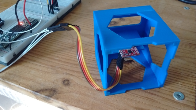
The calibration node do_calib expects IMU data to be published on the topic imu. The cal_imu.launch file is used to launch the ROS serial node and remap the topic:
<?xml version="1.0" ?>
<launch>

  <!-- Teensy.
       Use the defaults /dev/ttyACM0 (or teensy if dev rules updated) and 500000 -->
  <arg name="serial_port" default="/dev/ttyACM0"/>
  <arg name="baud_rate" default="500000"/>
  <node pkg="rosserial_python" type="serial_node.py"
  name="serial_node" output="screen">
    <param name="port" value="$(arg serial_port)"/>
    <param name="baud" value="$(arg baud_rate)"/>
    <remap from="/imu/data_raw" to="imu"/>
  </node>

  <!-- now "rosrun imu_calib do_calib" in a shell -->

</launch>
Once the serial node is running, execute the following command in another terminal to start the calibration process:
rosrun imu_calib do_calib
Follow the on-screen instructions to complete the calibration. After generating the calibration file, copy it to the rodney/config folder.
Node Modifications The changes to the imu_calib package are focused on the apply_calib.cpp and apply_calib.h files. Parameters are read from the parameter server to enable or disable functionality:
nh_private.param<bool>("null_accelerometer", null_accelerometer_, true);
nh_private.param<int>("null_accelerometer_samples", null_accelerometer_samples_, 100);
In the rawImuCallback function, code is added to calculate the mean accelerometer offsets at startup:
if(null_accelerometer_ == true)
{
  ROS_INFO_ONCE("Nulling accelerometer; do not move the IMU");

  // Recursively compute mean accelerometer measurements from corrected acceleration readings
  sensor_msgs::Imu corrected = *raw;
  accel_sample_count_++;

  calib_.applyCalib(raw->linear_acceleration.x,
               raw->linear_acceleration.y, raw->linear_acceleration.z,
               &corrected.linear_acceleration.x, &corrected.linear_acceleration.y,
               &corrected.linear_acceleration.z);

  accel_bias_x_ = ((accel_sample_count_ - 1) *
                    accel_bias_x_ + corrected.linear_acceleration.x) / accel_sample_count_;
  accel_bias_y_ = ((accel_sample_count_ - 1) *
                    accel_bias_y_ + corrected.linear_acceleration.y) / accel_sample_count_;
  accel_bias_z_ = ((accel_sample_count_ - 1) * accel_bias_z_ +
                   (corrected.linear_acceleration.z-9.80665)) / accel_sample_count_;

  if (accel_sample_count_ >= null_accelerometer_samples_)
  {
    ROS_INFO("Nulling accelerometers complete! (bias = [%.3f, %.3f, %.3f])",
              accel_bias_x_, accel_bias_y_, accel_bias_z_);
    null_accelerometer_ = false;
  }
}
These offsets are subtracted from the calibration-corrected values:
corrected.linear_acceleration.x -= accel_bias_x_;
corrected.linear_acceleration.y -= accel_bias_y_;
corrected.linear_acceleration.z -= accel_bias_z_;
Updating the Launch File
The following addition to the rodney.launch file launches the updated node and specifies the location of the calibration file:
<!-- Add calibration to raw imu data -->
<node pkg="imu_calib" type="apply_calib" name="imu_calib" output="screen">
  <param name="calib_file" value="$(find rodney)/config/imu_calib.yaml"/>
</node>
Data Fusion Configuration
The robot_localization.yaml file, found in the rodney/config folder, configures the data fusion process for the ekf_localization_node from the robot_localization package. This node combines IMU and raw odometry data to generate odometry data used by the navigation system.
The configuration matrix is structured as follows:
[ x position,     y position,     z position,
  roll,           pitch,          yaw,
  x velocity,     y velocity,     z velocity,
  roll velocity,  pitch velocity, yaw velocity,
  x acceleration, y acceleration, z, acceleration]
A "true" value in the matrix means the corresponding data will be used by the Extended Kalman Filter.
For the raw odometry data:
odom0_config: [false, false, false,
               false, false, false,
               true,  true,  false,
               false, false, true,
               false, false, false]
For the IMU data, two configurations can be tried:
- Using just the yaw velocity from the IMU:
imu0_config: [false, false, false,
              false, false, false,
              false, false, false,
              false, false, true,
              false, false, false]
- Including x and y velocities (ensure noise/error reduction):
imu0_config: [false, false, false,
              false, false, false,
              true, true, false,
              false, false, true,
              false, false, false]
Static Transforms
In the previous section, we introduced a static transform for the height of the robot base from the ground using a latched transform broadcast from the rodney.launch file:
<node pkg="tf2_ros" type="static_transform_publisher"
      name="base_footprint_broadcaster" args="0 0 0.09 0 0 0 /base_footprint /base_link"/>
With the addition of the LIDAR and IMU, we need to incorporate more static transforms. The measurements from the LIDAR need to be translated from its location to the center of the robot. Instead of adding multiple static transforms in the launch file, we'll write a single node to manage all the necessary static transforms.
Creating the Static Transform Broadcaster Node
In the rodney/src folder, add the static_broadcaster.py file. This Python script will create a node responsible for broadcasting the three static transforms, with the transforms being latched to ensure they are available to other nodes upon startup.
# Rodney robot static transform broadcaster

import sys
import rospy
import tf
import tf2_ros
import geometry_msgs.msg

def main(args):
    rospy.init_node('rodney_static_broadcaster', anonymous=False)
    rospy.loginfo("Rodney static broadcaster node started")

    broadcaster = tf2_ros.StaticTransformBroadcaster()

    # Static transform for the base_footprint to base_link
    st1 = geometry_msgs.msg.TransformStamped()
    st1.header.stamp = rospy.Time.now()
    st1.header.frame_id = "base_footprint"
    st1.child_frame_id = "base_link"
    st1.transform.translation.x = 0.0
    st1.transform.translation.y = 0.0
    st1.transform.translation.z = 0.09
    quat = tf.transformations.quaternion_from_euler(0.0, 0.0, 0.0)
    st1.transform.rotation.x = quat[0]
    st1.transform.rotation.y = quat[1]
    st1.transform.rotation.z = quat[2]
    st1.transform.rotation.w = quat[3]

    # Static transform for the base_link to laser
    st2 = geometry_msgs.msg.TransformStamped()
    st2.header.stamp = rospy.Time.now()
    st2.header.frame_id = "base_link"
    st2.child_frame_id = "laser"
    st2.transform.translation.x = 0.085
    st2.transform.translation.y = 0.0
    st2.transform.translation.z = 0.107
    quat = tf.transformations.quaternion_from_euler(0.0, 0.0, 0.0)
    st2.transform.rotation.x = quat[0]
    st2.transform.rotation.y = quat[1]
    st2.transform.rotation.z = quat[2]
    st2.transform.rotation.w = quat[3]

    # Static transform for the base_link to imu
    st3 = geometry_msgs.msg.TransformStamped()
    st3.header.stamp = rospy.Time.now()
    st3.header.frame_id = "base_link"
    st3.child_frame_id = "imu"
    st3.transform.translation.x = 0.0
    st3.transform.translation.y = 0.0
    st3.transform.translation.z = 0.058
    quat = tf.transformations.quaternion_from_euler(0.0, 0.0, 0.0)
    st3.transform.rotation.x = quat[0]
    st3.transform.rotation.y = quat[1]
    st3.transform.rotation.z = quat[2]
    st3.transform.rotation.w = quat[3]

    broadcaster.sendTransform([st1, st2, st3])

    # Static transforms are latched, so we only need to
Adding the Node to the Launch File
To ensure the node starts with the robot, add the following entry to the rodney.launch file:
<!-- Static transforms in the system -->
<node pkg="rodney" type="static_broadcaster.py" name="static_broadcaster_node"/>
By implementing this node, we streamline the process of broadcasting static transforms, making it easier to manage and extend in the future. This approach ensures that all necessary static transforms are available to any node that requires them, improving the robot's ability to accurately interpret sensor data relative to its frame of reference.
Updated Launch File
Here is the revised rodney.launch file, with the output="screen" parameter removed from nodes that are no longer under development or test to reduce the amount of log messages displayed in the terminal. This file also includes the new static transform broadcaster node and other updates mentioned in the previous sections.
<?xml version="1.0" ?>
<launch>
  <!-- Static transforms in the system -->
  <node pkg="rodney" type="static_broadcaster.py" name="static_broadcaster_node"/>

  <!-- Load each of the config files into the parameter server -->
  <rosparam command="load" file="$(find pan_tilt)/config/config.yaml"/>
  <rosparam command="load" file="$(find face_recognition)/config/config.yaml"/>
  <rosparam command="load" file="$(find head_control)/config/config.yaml"/>
  <rosparam command="load" file="$(find rodney_missions)/config/config.yaml"/>

  <!-- Launch the camera node from one of its launch files -->
  <include file="$(find raspicam_node)/launch/camerav2_1280x960.launch" />

  <!-- Start all the nodes that make up Rondey -->
  <!-- Starting with those written for the project -->
  <node pkg="pan_tilt" type="pan_tilt_node" name="pan_tilt_node"/>
  <node pkg="face_recognition" type="face_recognition_node.py" name="face_recognition_node"/>
  <node pkg="head_control" type="head_control_node" name="head_control_node"/>
  <node pkg="speech" type="speech_node" name="speech_node"/>
  <node pkg="rodney_missions" type="rodney_missions_node.py"
        name="rodney_missions" output="screen"/>
  <node pkg="rodney" type="rodney_node" name="rodney" output="screen">
    <rosparam command="load" file="$(find rodney)/config/config.yaml"/>
  </node>
  <node pkg="thunderborg" type="thunderborg_node.py" name="thunderborg_node">
    <rosparam command="load" file="$(find thunderborg)/config/config.yaml"/>
  </node>

  <!-- Teensy.
       Use the defaults /dev/ttyACM0 (or teensy if dev rules updated) and 500000 -->
  <arg name="serial_port" default="/dev/teensy"/>
  <arg name="baud_rate" default="500000"/>
  <node pkg="rosserial_python" type="serial_node.py" name="serial_node" output="screen">
    <param name="port" value="$(arg serial_port)"/>
    <param name="baud" value="$(arg baud_rate)"/>
  </node>

  <!-- The RPLidar and laser filter node
       Have created symbolic link for /dev/ttyUSBn to be rplidar -->
  <node pkg="rplidar_ros" type="rplidarNode" name="rplidar_node" output="screen">
    <param name="serial_port" type="string" value="/dev/rplidar"/>
    <param name="serial_baudrate" type="int" value="115200"/>
    <param name="frame_id" type="string" value="laser"/>
    <remap from="scan" to="scan_filter_input"/>
  </node>
  <node pkg ="laser_filters" type="scan_to_scan_filter_chain"
        name="scan_to_scan_filter_chain" output="screen">
    <rosparam command="load" file="$(find rodney)/config/laser_filter_config.yaml"/>
    <remap from="scan" to="scan_filter_input"/>
    <remap from="scan_filtered" to="scan"/>
  </node>

  <!-- The robot face -->
  <node pkg="homer_robot_face" type="RobotFace" name="RobotFace"/>

  <!-- Add calibration to raw imu data -->
  <node pkg="imu_calib" type="apply_calib" name="imu_calib" output="screen">
    <param name="calib_file" value="$(find rodney)/config/imu_calib.yaml"/>
  </node>

  <!-- Node to fuse motor encoder and IMU data for odom -->
  <node pkg="robot_localization" type="ekf_localization_node" name="ekf_localization_node">
    <remap from="odometry/filtered" to="odom"/>
    <rosparam command="load" file="$(find rodney)/config/robot_localization.yaml"/>
  </node>

</launch>
Code Improvements
I have implemented several subtle code refinements, primarily focused on enabling and disabling the LIDAR when the EaseRobot is in manual mode, as well as preventing uncontrolled robot movements during remote control.
Updates to the EaseRobot Missions Node
I have made subtle adjustments to this node, enabling it to control the LIDAR by starting and stopping the LIDAR motor. Although the request originates from the EaseRobot node, it is crucial that this node exercises control to ensure the LIDAR operates when autonomous navigation is requested in the future.
The motor startup and shutdown are accomplished via ROS service calls to the LIDAR node. The initial changes are found in the init function of the MissionsHelper class. We wait for the services to become available, create proxy calls to access the service, and then invoke the LidarEnable helper function to verify the LIDAR's current operational status.
# RPLidar services to start and stop the motor
rospy.wait_for_service('stop_motor')
rospy.wait_for_service('start_motor')
self.__rplidar_stop_motor_srv = rospy.ServiceProxy('stop_motor', std_srvs.srv.Empty)
self.__rplidar_start_motor_srv = rospy.ServiceProxy('start_motor', std_srvs.srv.Empty)
# LIDAR should be running but make sure
self.LidarEnable()
Next, I have added three helper functions to the MissionHelper class, which invoke the respective service and maintain a record of the LIDAR motor's current state.
# Function to enable the RPLidar
def LidarEnable(self):
    self.__rplidar_start_motor_srv()
    self.__lidar_on = True

# Function to disable the RPLidar
def LidarDisable(self):
    self.__rplidar_stop_motor_srv()
    self.__lidar_on = False

# Function to Toggle RPLidar on/off
def ToggleLidar(self):
    if(self.__lidar_on == True):
        self.LidarDisable()
    else:
        self.LidarEnable()
The final update involves modifying the Prepare class by introducing an additional elif statement within the execute function. This new condition checks if the received job identifier is 'J4', indicating a request to toggle the current state of the LIDAR.
elif parameters[0] == 'J4':
    # Toggle the LIDAR state
    self.__helper_obj.ToggleLidar()
These changes are part of ongoing enhancements to the EaseRobot project.
Updates to the EaseRobot Package
To enhance the functionality of the EaseRobot package, several key updates are planned for the rodney node. These changes aim to enable/disable the LIDAR using either the joystick or keyboard connected to the remote workstation during manual mode.
Additionally, a new issue has been identified where the robot continues using the last input velocities when the home network drops out temporarily during manual control. To address this, a new node named remote_heartbeat_node has been introduced in the rodney package. This node, running on the remote workstation, publishes a heartbeat message. The rodney node on the robot hardware now monitors this message: if the robot is in manual mode and the message isn't received for one second, velocities will automatically reset to zero.
Changes to rodney_node.cpp
To enable LIDAR control from the joystick, configure the appropriate button by adding the following line to the RodneyNode constructor.
nh_.param("/controller/buttons/lidar_enable", lidar_enable_select_, 2);
In the oystickCallback` function, incorporate the following conditional statement to toggle the LIDAR motor state when the corresponding joystick button is pressed:
// Button on controller selects to enable/disable the lidar function
if((manual_locomotion_mode_ == true) && (msg->buttons[lidar_enable_select_] == 1))
{
    std_msgs::String mission_msg;

    // Toggle the LIDAR on/off
    mission_msg.data = "J4";

    mission_pub_.publish(mission_msg);
    last_interaction_time_ = ros::Time::now();
}
Similarly, when the 'l' key is pressed on the keyboard, the motor state should be toggled. To achieve this, add the following "else if" construct to the keyboardCallBack function:
else if((msg->code == keyboard::Key::KEY_l) &&
       ((msg->modifiers & ~RodneyNode::SHIFT_CAPS_NUM_LOCK_) == 0))
{
    if(manual_locomotion_mode_ == true)
    {
        std_msgs::String mission_msg;

        // Toggle the LIDAR on/off
        mission_msg.data = "J4";

        mission_pub_.publish(mission_msg);
        last_interaction_time_ = ros::Time::now();
    }
}
remote_heartbeat_sub_ = nh_.subscribe
                        ("remote_heartbeat", 1, &RodneyNode::remHeartbeatCallback, this);
A callback function for when the message on this topic is received will store the time of the last message.
// Callback for remote heartbeat
void RodneyNode::remHeartbeatCallback(const std_msgs::Empty::ConstPtr& msg)
{
    // Remote heartbeat received store the time
    remote_heartbeat_time_ = ros::Time::now();
}
In the sendTwist function, it is essential to reset the velocities to zero if more than one second has elapsed since the last heartbeat message was received. The updated implementation of the sendTwist function is presented below:
void RodneyNode::sendTwist(void)
{
    geometry_msgs::Twist target_twist;

    // If in manual locomotion mode use keyboard or joystick data
    if(manual_locomotion_mode_ == true)
    {
        // Only allow stored keyboard or joystick values to set
        // the velocities if the remote heartbeat is running
        if((ros::Time::now() - remote_heartbeat_time_).toSec() < 1.0)
        {
            // Publish message based on keyboard or joystick speeds
            if((keyboard_linear_speed_ == 0) && (keyboard_angular_speed_ == 0))
            {
                // Use joystick values
                target_twist.linear.x = joystick_linear_speed_;
                target_twist.angular.z = joystick_angular_speed_;
            }
            else
            {
                // use keyboard values
                target_twist.linear.x = keyboard_linear_speed_;
                target_twist.angular.z = keyboard_angular_speed_;
            }
        }
        else
        {
            // Lost connection with remote workstation so zero the velocities
            target_twist.linear.x = 0.0;
            target_twist.angular.z = 0.0;
        }
    }
    else
    {
        // Use mission demands (autonomous)
        target_twist.linear.x = linear_mission_demand_;
        target_twist.angular.z = angular_mission_demand_;
    }

    // If not using the PID ramp to the target value.
    if (false == pid_enabled_)
    {
        ros::Time time_now = ros::Time::now();

        // Ramp towards are required twist velocities
        last_twist_ = rampedTwist(last_twist_, target_twist, last_twist_send_time_, time_now);

        last_twist_send_time_ = time_now;

        // Publish the Twist message using the ramp value
        twist_pub_.publish(last_twist_);
    }
    else
    {
        // Publish the Twist message using the target value
        twist_pub_.publish(target_twist);
    }
}
Next, we will create the remote_heartbeat_node.cpp file within the EaseRobot/src directory. Note that this node is designed to run on a remote workstation, allowing manual control of the robot, rather than on the robot's hardware itself. The purpose of this node is to simply broadcast the heartbeat message at a frequency of 5Hz.
// This heartbeat node is not to be run on the robot platform but on a remote worksation
// when either the keyboard or joystick nodes are being used to teleop the robot. If the
// message sent by this node is missed for 1 second, the robot will stop using the keyboard
// and joystick stored values to drive the motors.
#include <ros/ros.h>
#include <std_msgs/Empty.h>

int main(int argc, char **argv)
{
    ros::init(argc, argv, "remote_heartbeat");
    ros::NodeHandle n;

    ros::Publisher remote_heartbeat_pub = n.advertise<std_msgs::Empty>("remote_heartbeat", 1);

    std::string node_name = ros::this_node::getName();
    ROS_INFO("%s started", node_name.c_str());

    ros::Rate r(5); // 5Hz

    std_msgs::Empty beat;

    while(ros::ok())
    {
        remote_heartbeat_pub.publish(beat);

        ros::spinOnce();
        r.sleep();
    }

    return 0;
}
Robot Hardware
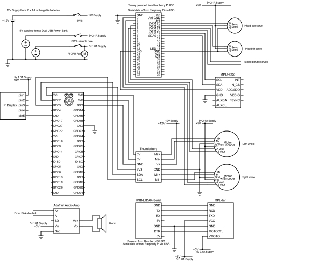
Summary
In this section, Design Goal 4 has been successfully achieved, and an IMU has been integrated to enhance odometry accuracy.
The upcoming article will focus on integrating packages that utilize LIDAR for autonomous navigation. This includes generating maps based on LIDAR and odometry transform data. We will utilize rviz to define target poses, enabling the robot to autonomously navigate to specified locations.
Introduction
The EaseRobot project is a hobbyist endeavor aimed at creating an autonomous household assistant using ROS (Robot Operating System). This article marks the seventh installment in the series documenting the project's development.
Background
In the initial phase, we outlined our robot's requirements by selecting its primary mission and breaking it down into several Design Goals to facilitate implementation.
The mission, inspired by the article "Let's build a robot!", involves creating a robot capable of recognizing family members and functioning as a messenger and reminder. For instance, one could say, "Robot, remind (PersonName) to pick me up from the station at 6 pm." Even if the intended recipient's phone is on silent or they are otherwise occupied, the robot would navigate autonomously through the house, locate the individual, and deliver the message.
The specific Design Goals identified for this mission are:
- Design Goal 1: Implement camera-based face detection and recognition to identify individuals and display messages.
- Design Goal 2: Integrate facial expression recognition and speech synthesis capabilities for effective communication.
- Design Goal 3: Enable remote control of locomotion via keyboard and/or joystick.
- Design Goal 4: Integrate a laser range finder or similar sensor for navigation assistance.
- Design Goal 5: Achieve autonomous navigation capabilities using the ROS Navigation Stack.
- Design Goal 6: Implement task assignment and completion notification functionalities.
In the previous installment, we successfully integrated a spinning LIDAR and an IMU to fulfill Design Goal 4, enhancing navigation accuracy. In this article, we will utilize the ROS Navigation Stack to achieve autonomous locomotion for EaseRobot. This involves leveraging ROS packages for SLAM (Simultaneous Localization and Mapping), probabilistic localization systems, and global/local navigation planning to progress towards fulfilling Design Goal 5.
Autonomous Navigation Architecture
In ROS, a collection of packages can be combined to enable autonomous navigation. Although the concept of ROS stacks is outdated, the term "Navigation Stack" is still widely used. This refers to a set of packages that work together to facilitate robot navigation. In this tutorial, we will focus on configuring and launching existing ROS packages, rather than writing new code. It's essential to familiarize yourself with the configurable parameters of each package by consulting the ROS Wiki.
Environment Mapping
To navigate effectively, our robot needs a map of its surroundings. We'll use the gmapping package to create a map from sensor data recorded on a Linux workstation. Alternatively, you can run the node on the robot's hardware. Gmapping provides laser-based Simultaneous Localization and Mapping (SLAM) capabilities. The resulting map can be visualized in rviz, as shown below.
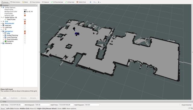
The map is stored in two files: a.yaml file and a.pgm file. You can edit the.pgm file using image editing tools to refine the map and restrict areas the robot should avoid.
While it's possible to create maps in real-time, most tutorials recommend recording sensor data and then generating the map from the recorded data. This approach allows you to experiment with different parameter settings. I prefer a hybrid approach, where you record data and visualize the map in rviz as it's created. This ensures you don't miss critical areas of the map.
To create the map, drive your robot slowly in manual mode, revisiting locations to improve map quality. I'll provide instructions on recording data and creating the map in the "Using the Code" section.
Once we have a map, the robot needs access to it. In ROS, this is achieved using topics. The map_server package provides the necessary nodes, including a latched topic that contains the map. This topic is not continually published, but rather passed to new nodes that require the map. The package also includes the map_saver node, which saves the map created by gmapping to disk.
To launch the map_server node on the robot hardware, we'll add the following code to the easerobot.launch file:
<arg name="map_file" default="second_floor"/>
<node pkg="map_server" type="map_server" name="map_server"
args="$(find easerobot)/maps/$(arg map_file).yaml" output="screen"/>
This implies that we'll store our map files in a new folder called maps within the easerobot package. If we don't provide a map_file parameter when calling the launch file, the default value of second_floor will be used.
Robot Localization: The Key to Navigation
To complete the navigation system, we need to enable our EaseRobot to determine its location and orientation in the environment. This process, known as robot localization, is crucial for the robot to understand its surroundings and make informed decisions. Since the odom and laser sensors are not perfect, the robot will maintain a list of possible locations, known as poses, and continually update and refine this list as it moves.
Introducing Adaptive Monte Carlo Localization (AMCL)
To achieve robot localization, we will utilize the amcl package, which stands for Adaptive Monte Carlo Localization. Fortunately, we only need to configure and launch the package, without delving into the intricacies of AMCL. For those interested in learning more, a good starting point is the Wikipedia page on AMCL.
Configuring the AMCL Node
As with most ROS packages, we will configure the amcl node by loading configuration data onto the parameter server. This data is stored in the amcl_config.yaml file, located in the EaseRobot/config folder. Below is an example of the configuration file, which can be customized to suit specific needs.
# Overall filter parameters
min_particles: 500
max_particles: 3000
kld_err: 0.05
kld_z: 0.99
update_min_d: 0.2
update_min_a: 0.5
resample_interval: 1
transform_tolerance: 0.5
recovery_alpha_slow: 0.0
recovery_alpha_fast: 0.0
gui_publish_rate: 1.0

# Laser model parameters
laser_max_beams: 30
laser_z_hit: 0.5
laser_z_short: 0.05
laser_z_max: 0.05
laser_z_rand: 0.5
laser_sigma_hit: 0.2
laser_lambda_short: 0.1
laser_likelihood_max_dist: 2.0
laser_model_type: likelihood_field

# Odometry model parameters
odom_model_type: diff
odom_alpha1: 0.2
odom_alpha2: 0.2
odom_alpha3: 0.8
odom_alpha4: 0.2
odom_alpha5: 0.1
odom_frame_id: odom
base_frame_id: base_footprint
Launching the AMCL Node
To launch the amcl node with the specified configuration, we will add the following code to the EaseRobot.launch file:
<node pkg="amcl" type="amcl" name="amcl" output="screen">
  <rosparam command="load" file="$(find EaseRobot)/config/amcl_config.yaml"/>
  </node>
Important Notes
It's worth noting that most of the parameter changes made to the nav stack relate to transform tolerances and sample frequencies. Given the complex calculations required, we need to ensure that the Raspberry Pi can handle these tasks efficiently.
Navigating Through the Environment
Now that we have a solid foundation, it's time to focus on the crux of the matter: planning a route for our EaseRobot to navigate from one point to another. To achieve this, we'll be utilizing the move_base package, which relies on data from various sources, including the map, odom, laser, and amcl. This package is responsible for plotting the most efficient route while adapting to changes in the environment, such as unexpected obstacles or moving objects.
Costmaps: The Key to Navigation
The move_base package employs two types of costmaps: global and local. A costmap is a visual representation of the environment, highlighting areas that are favorable or unfavorable for the robot to occupy. The global costmap is based on the static map and remains unchanged, providing a broad overview of the environment. In contrast, the local costmap is dynamic, updating in real-time as the robot moves, and focuses on the immediate surroundings.
Configuring the Planners
The move_base package supports various global and local planners, as long as they conform to the nav_core::BaseGlobalPlanner and nav_core::BaseLocalPlanner interfaces, respectively. This flexibility allows developers to create custom planners or utilize existing ones. In this case, we'll be using the global_planner and dwa_local_planner.
Configuration Files
To set up the move_base package, we'll create several configuration files, stored in the EaseRobot/config folder, which will be loaded into the parameter server. One such file is base_local_planner_params.yaml, which defines the parameters for the local planner, including controller frequency, planner selection, and various velocity and acceleration limits.
Tuning the Local Planner
The local planner's performance is highly dependent on the values assigned to its parameters. These values can be adjusted dynamically using dynamic reconfiguration, and their optimal settings vary depending on the robot's environment and characteristics. For instance, increasing the maximum speed and rotational velocity may seem beneficial, but it can lead to the robot getting stuck in tight spaces. It's essential to carefully calibrate these parameters to ensure smooth navigation.
Costmap Parameters
Both global and local costmaps share some common parameters, while others are specific to each type. Understanding these parameters is crucial for fine-tuning the navigation system to suit the EaseRobot's unique needs.
Deploying and Testing the Code
To test and deploy the code, I'll be using a Linux PC, referred to as the workstation, to handle the test tools and manual control nodes, while the code will run directly on the robot hardware.
Setting Up ROS Packages on the Raspberry Pi (Robot Hardware)
- Prepare the Workspace:
If you haven’t already set up a catkin workspace on the Raspberry Pi, follow these steps:
$ mkdir -p ~/ease_robot_ws/src
$ cd ~/ease_robot_ws/
$ catkin_make
- Add Packages:
Transfer the following ROS packages to the ~/ease_robot_ws/src directory on the Raspberry Pi:
face_recognition
face_recognition_msgs
head_control
imu_calib
pan_tilt
ease_robot
ease_robot_missions
ros-keyboard
rplidar-ros
servo_msgs
speech
tacho_msgs
thunderborg
- Build the Workspace:
Navigate to the workspace and build the packages:
$ cd ~/ease_robot_ws/
$ catkin_make
Ensure the build completes without any errors.
- Teensy Compilation:
Compile and upload the sketch to the Teensy 3.5 as per your project's requirements.
Setting Up ROS Packages on the Workstation
- Create the Workspace:
On the workstation, set up a new catkin workspace with the following commands:
$ mkdir -p ~/test_ws/src
$ cd ~/test_ws/
$ catkin_make
- Add Packages:
Place the following ROS packages into the ~/test_ws/src directory:
ease_robot
joystick
ros-keyboard
*Build the Workspace:
Change to the workspace directory and build the packages:
$ cd ~/test_ws/
$ catkin_make
Verify that the build completes without any errors.
Time-Saving Tips for ROS Command Entry
When managing ROS (Robot Operating System) on both your workstation and Raspberry Pi, you often find yourself typing the same commands repeatedly across different terminals. To streamline this process, consider these time-saving tips:
- Automate Command Execution on the Raspberry Pi:
To avoid typing source devel/setup.bash every time you open a new terminal session on the Raspberry Pi, you can automate this process by adding the command to your .bashrc file. Follow these steps:
$ cd ~/
$ nano .bashrc
Add the following line to the end of the .bashrc file:
source /home/ubuntu/ease_robot_ws/devel/setup.bash
Save the file and exit. This change ensures that the necessary ROS environment variables are set
automatically each time you start a new terminal session.
- Simplify Command Entry on the Workstation:
On your workstation, you can also streamline your workflow by defining an alias that sets up the ROS environment and specifies the ROS master URI. Add the following alias to your workstation's .bashrc file:
alias ease_robot='source ~/test_ws/devel/setup.bash; \
export ROS_MASTER_URI=http://ubiquityrobot:11311'
With this alias in place, you only need to type ease_robot in the terminal to execute both commands simultaneously, saving you from repetitive typing.
- Use TAB Completion for Efficiency:
Many ROS tools support TAB completion, which can speed up command entry. For example, if you type rosrun rosserial_ and press the TAB key, the terminal will automatically complete the command to rosrun rosserial_python if that is the only option. This feature helps to reduce errors and speeds up command entry.
By integrating these tips into your workflow, you'll enhance your productivity and make working with ROS more efficient.
Monitoring EaseRobot's Log Files
As EaseRobot explores its surroundings, it's essential to keep track of its log messages. While these messages are displayed in the terminal where you launched the code, this isn't practical if the robot is moving around in a different room. To overcome this limitation, you can remotely monitor the log files from the control station using the following steps:
Set the ROS Master URI environment variable to point to the EaseRobot's ROS master node:
export ROS_MASTER_URI=http://ubiquityrobot:11311
Launch the ROS console tool:
rqt_console
This will allow you to view EaseRobot's log messages in real-time, even when it's operating in a different location.
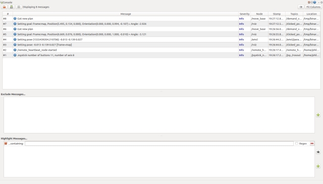
Building a Map with EaseRobot
To begin, we'll start by launching the necessary nodes on the robot's hardware, excluding the navigation stack. Open a terminal and run the following commands:
$ source ease_robot_ws/devel/setup.bash
$ roslaunch ease_robot ease_robot.launch no_nav:=True
Next, switch to your workstation and launch the remote control nodes using the following commands:
$ source test_ws/devel/setup.bash
$ export ROS_MASTER_URI=http://ubiquityrobot:11311
$ roslaunch ease_robot remote.launch
You should now see a small window titled "ROS keyboard input". Make sure this window has focus when entering keyboard commands.
Now, let's record the transforms and laser scan messages to create a map from the recorded data. Open a new terminal and start recording with the following commands:
$ export ROS_MASTER_URI=http://ubiquityrobot:11311
$ rosbag record -O data.bag /scan /tf
To visualize the map creation process, we'll launch the slam_gmapping node. In a new terminal on your workstation, run the following commands:
$ export ROS_MASTER_URI=http://ubiquityrobot:11311
$ rosparam set slam_gmapping/xmax 10
$ rosparam set slam_gmapping/ymax 10
$ rosparam set slam_gmapping/xmin -10
$ rosparam set slam_gmapping/ymin -10
$ rosparam set slam_gmapping/delta 0.05
$ rosrun gmapping slam_gmapping
Alternatively, you can use the mapping_launch package, which includes a launch file called mapping.launch. This package is available in the Robotics-test-code folder.
In another terminal on your workstation, launch rviz using the following commands:
$ source test_ws/devel/setup.bash
$ export ROS_MASTER_URI=http://ubiquityrobot:11311
$ roslaunch ease_robot rviz.launch
Configure rviz as follows:
- Set the fixed frame to "map"
- Display the /scan topic as LaserScan
- Display the base_link as TF
- Display the /map topic as Map
Using the joystick and/or keyboard, enter manual mode, ensure the LIDAR motor is running, and manually drive the EaseRobot around its environment. Move slowly and visit each location at least twice. You should see the map being created in real-time on rviz.
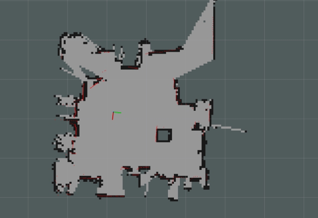
Saving and Regenerating the Map with EaseRobot
Now that you've created a map, press Ctrl-C in the terminal running rosbag to stop recording messages.
Next, save the map visible in rviz to disk. With slam_gmapping still running, enter the following command in the terminal that was running rosbag:
$ rosrun map_server map_saver -f my_first_map
This will save two files: my_first_map.yaml and my_first_map.pgm.
If you'd like to regenerate the map from the rosbag file with different gmapping parameters, you can do so now. First, shut down all terminals and the robot. Then, restart your workstation and follow these steps:
- Regenerating the Map
Open a new terminal and start the ROS master:
$ roscore
In another terminal, set the required gmapping parameters using rosparam:
$ rosparam set use_sim_time true
$ rosrun gmapping slam_gmapping
In a third terminal, playback the recorded rosbag file:
$ rosbag play --clock data.bag
Sit back and let gmapping recreate the map. If you'd like, you can start rviz (without setting the ROS_MASTER_URI) and watch the map being created in real-time.
Once the playback is complete, save the new map to disk:
$ rosrun map_server map_saver -f my_second_map
Feel free to experiment with different gmapping configuration parameters and playback the recorded bag file to see how they affect the generated map.
Autonomous Navigation: Bringing EaseRobot to Life
Now, let's dive into the most exciting part of our project – autonomous navigation. To get started, we'll need to launch all the necessary nodes on the EaseRobot's hardware. You can use the default map, or specify your own by adding "map_file:=my_first_map" to the end of the roslaunch command.
On the EaseRobot's hardware, run the following commands:
$ source ease_ws/devel/setup.bash
$ roslaunch ease ease.launch
Next, on the workstation, run the following commands to start the remote control node:
$ source test_ws/devel/setup.bash
$ export ROS_MASTER_URI=http://ubiquityrobot:11311
$ roslaunch ease remote.launch
You should see a small window titled "ROS keyboard input" appear. Make sure to focus on this window when entering keyboard commands.
In another terminal on the workstation, launch rviz using the following commands:
$ source test_ws/devel/setup.bash
$ export ROS_MASTER_URI=http://ubiquityrobot:11311
$ roslaunch ease rviz.launch
Visualizing the Robot's Environment
Configure rviz to display the EaseRobot's model or base_link axis, laser scan, map, and pose estimates. Ensure that the map is set as the fixed frame.
As we can see from the display, the laser scan doesn't align with the map, and the pose estimates are scattered. Before we can give the EaseRobot a navigational goal, we need to improve its localization.
The image below shows the EaseRobot's poor localization. The red lines represent the laser scan, while the green arrows indicate the pose estimates.
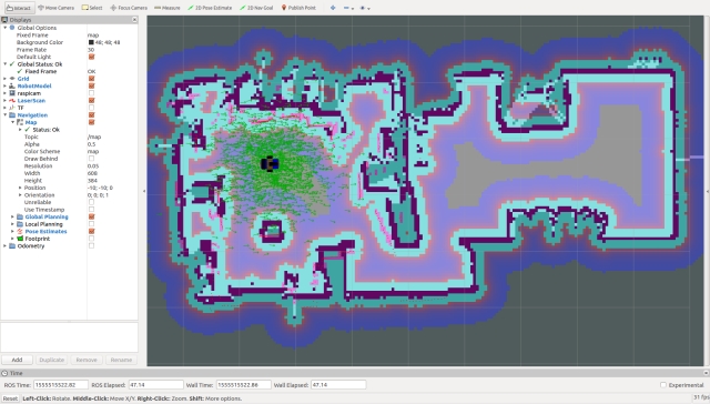
Our first task is to improve the EaseRobot's localization using rviz. To do this, click the "2D Pose Estimate" button and estimate the robot's real location and pose. Then, click and drag the large green arrow on the map to set the initial pose. Repeat this process until the laser scan aligns with the map.
Now that we have a good initial pose, let's refine the pose estimates by driving the EaseRobot around in manual mode. A good maneuver to try is spinning on the spot. As you move the robot, you should see the pose estimates converging on the robot's position.
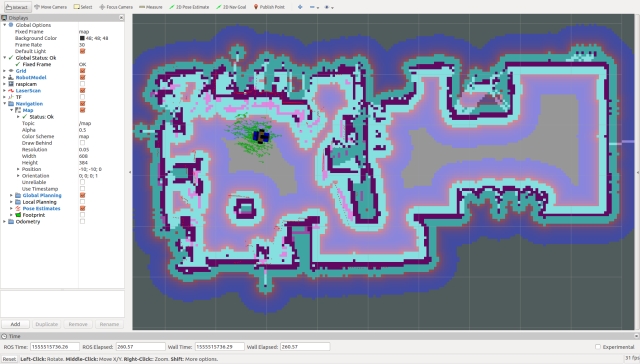
Next, we'll set a navigation goal for the EaseRobot. But first, let's take a look at the costmaps that will be used for planning the route. In rviz, select Global Planning to display the Global Costmap. I recommend selecting "Draw Behind" to wash out the map behind the main map.
The costmap shows the open spaces the planner will try to use and the riskier areas, such as up against a wall.
The Global Costmap is constructed from the main map and will be used to plan an ideal route. However, the actual movement of the EaseRobot will be governed by the Local Costmap, which will be generated on the fly as sensor data arrives. This allows the robot to avoid objects that weren't present when the map was created, such as a sleeping pet.
Select Local Planning in rviz to display the Local Costmap. I prefer to superimpose this map on top of the main map.
Now, set the target goal pose by clicking the "2D Nav Goal" button and clicking/dragging the large green arrow on the map to set the goal. Note that I've left the EaseRobot in manual mode, so it won't move yet. This gives us a chance to examine the global plan, shown as a thin green line in the image below.
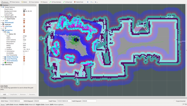
To put the EaseRobot into autonomous mode, give the ROS keyboard input window focus and press the "1" key (not on the numeric keypad). This requests the robot to run mission 1, which is currently empty, so it will take the robot out of manual mode and allow the navigation stack to generate velocities that will be sent to the motor controller.
With any luck, the EaseRobot will navigate to the goal pose, and you can monitor its progress on rviz. In the image below, the robot has arrived at the goal.
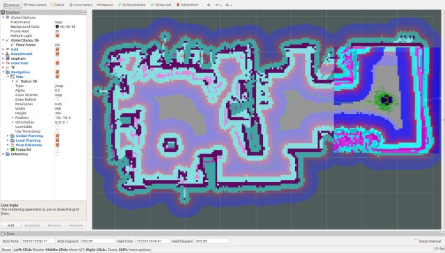
I've noticed that after setting multiple poses to move to, the navigation stack sometimes fails to calculate a route, despite a clear path on the costmaps. To clear this issue, run the following command on the workstation:
$ rosservice call /move_base/clear_costmaps
Summary
In this segment, we've successfully integrated autonomous navigation capabilities into EaseRobot.
In our upcoming article, we'll delve into the process of programmatically setting navigation objectives and incorporating facial recognition functionality into a mission. This will enable EaseRobot to roam freely around the house, searching for the intended recipient of the message.
Introduction
The EaseRobot project is a hobbyist robotic project aimed at designing and constructing an autonomous house-bot using ROS (Robot Operating System). This article marks the eighth installment in the series documenting the project's progress.
Background
In the initial phase, we defined the requirements for our robot by selecting a primary mission and breaking it down into specific Design Goals for clarity and manageability.
The mission, inspired by the article "Let's build a robot!", focuses on creating a robot capable of recognizing family members and functioning as a messenger and reminder. For instance, one could say, "Robot, remind (PersonName) to pick me up from the station at 6 pm." Even if the intended recipient's phone is on silent or they are occupied, the robot autonomously navigates through the house, locates the individual, and delivers the message.
The Design Goals established for this mission include:
- Design Goal 1: Implement camera-based face detection and identification to display messages for recognized individuals.
- Design Goal 2: Integrate capabilities for facial expressions and speech synthesis to effectively deliver messages.
- Design Goal 3: Enable locomotion control via remote keyboard and/or joystick.
- Design Goal 4: Incorporate a laser range finder or similar sensor to aid in navigation.
- Design Goal 5: Achieve autonomous locomotion, previously implemented using the ROS Navigation Stack.
- Design Goal 6: Implement task assignment and completion notification functionalities.
In the previous installment, we integrated the ROS Navigation Stack to achieve autonomous locomotion for EaseRobot, setting navigation goals using the visualization tool rviz. In this article, we will further enhance EaseRobot by adding mission-specific code to navigate different areas of the house and locate specific individuals to deliver messages. Locations to visit will be defined in a yaml file.
To support these enhancements, we will update the ease_robot and ease_robot_missions packages, and introduce a new package to interface LEDs and pushbuttons with the Raspberry Pi GPIO.
Revisiting State Machines with Smach
In our previous tutorial, we delved into the world of state machines using the Smach ROS package. We designed a hierarchical state machine that incorporated a lower-level state machine for the greeting mission (Mission 2). The beauty of this design lies in its modularity, making it easy to integrate new missions by simply adding lower-level state machines. In this installment, we'll take it a step further by introducing two new missions as lower-level state machines. Mission 1 will focus on delivering messages, while Mission 4 will enable the EaseRobot to return to its home location.
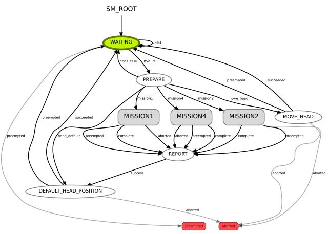
Before we dive into the implementation of these new missions, let's first explore how to integrate a bi-colored LED, two pushbuttons, and update the EaseRobot package to transmit the new mission data to the state machine.
Expanding EaseRobot's Capabilities with GPIO
In addition to the touch screen, we're going to integrate two pushbuttons to enable users to input commands to the EaseRobot. This is necessary because the screen, being part of the robot's head, may not always be in an accessible position for user interaction. Each pushbutton will have dual functions, depending on whether the robot is currently executing a mission or not.
The first pushbutton, identified by its black color, will perform the following functions. When no mission is running and the button is pressed, the robot's head will adjust to a position suitable for user input/output on the screen. If a mission is in progress and the button is pressed, a command will be sent to cancel the current mission.
The second pushbutton, identified by its yellow color, will carry out the following functions. When no mission is running and the button is pressed, a command will be issued to execute the "Go Home" mission, which navigates the robot to a predetermined home location. During certain mission states, user acknowledgement is required, such as when the robot delivers a verbal message. In this case, pressing the yellow pushbutton will send an acknowledgement message to the state machine.
To complement the pushbuttons, we'll also add a bi-colored LED to the robot's hardware. When the EaseRobot is not executing a live mission, the LED will glow green, and when a mission is in progress, it will glow red.
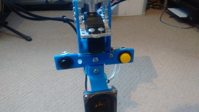
Instead of incorporating the GPIO code into the EaseRobot package, we'll create a new package to handle GPIO operations, promoting code reuse. We'll write this new node using Python, leveraging an existing library for accessing the Raspberry Pi GPIO. Our ROS package, called pi_io, is located in the pi_io folder. Within this package, we'll create a ROS service to control the state of the GPIO output lines and define a custom message that will be published when one of the pushbuttons changes state.
The EaseRobot package contains all the standard ROS files and folders, including the msg folder, which holds the gpio_input.msg file that defines a custom ROS message. This message consists of two parameters: an index that refers to a specific GPIO pin, and a value that represents the current state of that pin.
The srv folder contains the gpio_output.srv file, which defines a custom ROS service. This service takes two parameters: an index that indicates which GPIO pin to set, and a value to set that pin to. The service returns a boolean success value, which is always true in the case of the Raspberry Pi, as it cannot provide feedback on the state of its GPIO pins.
The src folder contains the Python code for the node in the pi_io_node.py file. The main function initializes the ROS node and creates an instance of the PiGpioNode class. This class constructor maps the actual GPIO pins to the index values used in the message and service, and sets up the GPIO pins as inputs or outputs. It also attaches event callbacks to the input pins, which will trigger when the pins go high.
The class constructor then registers the service and message topic with ROS, and creates two timers to debounce the pushbuttons. The callback functions for the service and input events are also defined. The service callback sets the GPIO output to the specified value and returns true, while the input callbacks publish a message on the gpio/input_cmd topic when a pushbutton is pressed, after checking for button bounce.
Finally, an updated circuit diagram is provided, showing how the bi-colored LED and pushbuttons are connected to the Raspberry Pi GPIO pins.
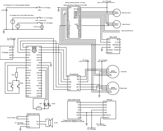
EaseRobot System Updates
To enhance the functionality of our EaseRobot system, we need to make some significant updates to the EaseRobot node. Specifically, we will modify the node to control the LED state and monitor the pushbutton topic. Additionally, we will enable the node to provide mission data for the two new missions.
Updating the Launch File
The first step is to update the ease_robot.launch file in the launch folder. This file is responsible for configuring and launching all the ROS nodes that make up our system. We need to add the new pi_io node to the launch file so that the new code runs when we launch the robot code.
To achieve this, we will add the following line to the launch file:
<node pkg="pi_io" type="pi_io_node.py" name="pi_io_node"/>
Configuring Waypoints
To enable the robot to navigate to various locations in the house, we will provide it with a list of waypoints stored in a YAML file. We will modify the EaseRobot node to accept the filename as an argument at launch. The waypoint file will have the same name as the map file with _patrol appended to the name. For example, if the map file is called second_floor, the corresponding waypoint file will be named second_floor_patrol.yaml.
We will update the launch file to pass the filename as an argument to the EaseRobot node using the following code:
<node pkg="ease_robot" type="ease_robot_node" name="ease_robot" args="-m $(find ease_robot)/maps/$(arg map_file)_patrol.yaml" output="screen"> <rosparam command="load" file="$(find ease_robot)/config/config.yaml"/> </node>
Waypoint File Structure
The waypoint file contains a list of waypoints, each with an x and y location and a direction (orientation) represented as a quaternion. The waypoints should start with w1 and be consecutive. The robot will visit each waypoint in ascending and then descending order when searching for the person to deliver the message to. The file should also include a home waypoint that the robot will navigate to when instructed to "Go Home".
Here is an example of a waypoints file:
# Waypoints must start at w1 and be consecutive
# Also have an home location
w1:
  position:
    x: -0.328835725784
    y: -0.529747009277
  orientation:
    x: 0.0
    y: 0.0
    z: 0.273852223218
    w: 0.961771781577
w2:
  position:
    x: 1.31689155102
    y: -0.944578707218
  orientation:
    x: 0.0
    y: 0.0
    z: 0.732759099845
    w: 0.680488134793
w3:
  position:
    x: 3.66307258606
    y: -0.040109038353
  orientation:
    x: 0.0
    y: 0.0
    z: 0.413215093458
    w: 0.910633453448
w4:
  position:
    x: 6.55329608917
    y: 1.04117441177
  orientation:
    x: 0.0
    y: 0.0
    z: 0.914737463209
    w: -0.404048726519
home:
  position:
    x: 0.0451934337616
    y: 0.0451934337616
  orientation:
    x: 0.0
    y: 0.0
    z: 0.224733375634
    w: 0.974420294265
Enhancements to the EaseRobot Missions Package
To facilitate the addition of new missions, we've made some adjustments to the EaseRobot missions node. Specifically, we've modified the EaseRobot_missions_node.py file and introduced two new files: take_message_to.py and go_home.py, which house the lower-level state machines.
Let's delve into the details of these two new state machines.
Mission 1 - "Deliver a Message"
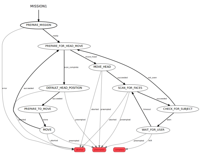
This mission is the culmination of our previous efforts. The entire code for this state machine is contained within the take_message_to.py file.
We enter this lower-level state machine through the PREPARE_MISSION state. The mission data passed to this state comprises the waypoint filename, the ID of the intended recipient, and the message to be delivered. These parameters are separated by the '|' character, so the first step is to split the data into its three constituent parts. The state machine then loads the waypoint file and, since we're navigating autonomously, ensures that the LIDAR is enabled. If the file is successfully opened and the waypoints are read, the state machine transitions to the PREPARE_FOR_HEAD_MOVE state. Conversely, if an error occurs, the mission is aborted, and the state machine returns to the higher-level root state machine.
Mission 4 - "Return to Base"
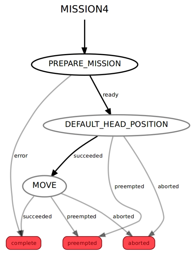
The entire code for this state machine is housed within the go_home.py file.
We access this lower-level state machine through the PREPARE_MISSION state. The mission data passed to this state includes the filename of the waypoints. The state machine loads the specified waypoint file, creates a navigation goal for the home waypoint, and enables the LIDAR to facilitate autonomous navigation. If the file is successfully read and the home waypoint is identified, the state machine transitions to the DEFAULT_HEAD_POSITION state. Conversely, if an error occurs during the process, the state machine returns to the higher-level root state machine.
Modifications to the Root State Machine
To complete the integration of the new missions, we need to make some adjustments to the EaseRobot_missions_node.py file, which houses the root state machine. This involves incorporating the lower-level state machines as individual states.
We've already implemented code to return the default head position, but since we've added a job to set the head to a user-input angle, we need to define this position. This requires minor changes to the EaseRobot_missions_node.py file to accommodate this functionality.
The MissionsHelper class constructor now includes code to read the angle used for the user input position from the parameter server, using radians for angle values.
self.__user_input_position_pan = rospy.get_param("head/user_position/pan", 0.0)
self.__user_input_position_tilt = rospy.get_param("head/user_position/tilt", -0.5)
The class also includes a new function to return these values.
def UserInputPosition(self):
return self.__user_input_position_pan, self.__user_input_position_tilt
The PREPARE state of the root state machine now needs to include code not only to set the user input angle when requested but also to transition to the new lower-level state machines if requested. The complete code for the PREPARE state is shown below.
# The PREPARE state
class Prepare(State):
def init(self, helper_obj):
State.init(self, outcomes=['mission1','mission2',
'mission4','done_task','head_default','move_head'],
input_keys=['mission'],
output_keys=['mission_data','start','user_data_absolute',
'user_data_pan','user_data_tilt'])
self.__helper_obj = helper_obj

def execute(self, userdata):
    # Based on the userdata, either change state to the required mission or
    # carry out a single job
    retVal = 'done_task';

    # Split into parameters using '^' as the delimiter
    parameters = userdata.mission.split("^")

    if parameters[0] == 'M1':
        # Mission 1: search for a known person and deliver a message
        userdata.mission_data = parameters[1]
        retVal ='mission1'
    elif parameters[0] == 'M2':
        # Mission 2: scan for faces and greet those known
        userdata.start = True
        retVal ='mission2'
    elif parameters[0] == 'M4':
        # Mission 4: go home
        userdata.mission_data = parameters[1]
        retVal ='mission4'
    elif parameters[0] == 'J1':
        # Simple Job 1: play a supplied wav file and move the face lips
        self.__helper_obj.Wav(parameters[1], parameters[2])
    elif parameters[0] == 'J2':
        # Simple Job 2: speak the supplied text and move the face lips
        self.__helper_obj.Speak(parameters[1], parameters[2])
    elif parameters[0] == 'J3':
        # Simple Job 3: move the head/camera
        if 'c' in parameters[1]:
            # Move to default position
            retVal = 'head_default'
        elif 'i' in parameters[1]:
            # Move to user input position
            pan_position, tilt_position = self.__helper_obj.UserInputPosition()
            userdata.user_data_absolute = True
            userdata.user_data_pan = pan_position
            userdata.user_data_tilt = tilt_position
            retVal ='move_head'
        else:
            relative_request_pan, relative_request_tilt =
                 self.__helper_obj.CameraManualMove(parameters[1]+parameters[2])
            userdata.user_data_absolute = False
            userdata.user_data_pan = relative_request_pan
            userdata.user_data_tilt = relative_request_tilt
            retVal ='move_head'
    elif parameters[0] == 'J4':
        # Simple job to toggle the LIDAR on/off
        self.__helper_obj.ToggleLidar()

    return retVal
The remaining changes involve adding the new lower-level state machines to the root state machine in the RodneyMissionNode class.
This is an example of adding a new state machine to the root:
# Create a sub-state machine for mission 1 - take a message to
self.__sm_mission1 = missions_lib.Mission1StateMachine(self.__missions_helper)
Now add the sub-state machine for mission 1 to the top-level one
StateMachine.add('MISSION1',
self.__sm_mission1,
transitions={'complete':'REPORT','preempted':'REPORT','aborted':'REPORT'})
We must also make a call to preempt the lower-level state machine when a message to cancel a mission is received. The CancelCallback function now looks like this:
# Callback for cancel mission message
def CancelCallback(self, data):
# If a sub-state machine for a mission is running, request it be preempted
if self.__sm_mission1.is_running():
self.__sm_mission1.request_preempt()
elif self.__sm_mission2.is_running():
self.__sm_mission2.request_preempt()
elif self.__sm_mission4.is_running():
self.__sm_mission4.request_preempt()
Hardware Components of EaseRobot
For a detailed understanding of the circuitry, a comprehensive circuit diagram is provided in the diagrams zip folder. Additionally, a visual representation of the nodes and topics is available in the rqt_graph image, also included in the zip folder.
A thorough list of materials used in the project so far can be accessed here.
In the first part of this tutorial, I mentioned the Ubiquity Robot Image, which is utilized on the Raspberry Pi.
Summary
As we near the completion of our initial vision for EaseRobot, this final installment will focus on the following key objectives:
- Web-based Mission Assignment: We will explore how to assign missions and mission data through a web browser, thereby fulfilling Design Goal 6.
- Automated Greeting Mission: We will configure the robot to execute Mission 2, the greeting mission, upon startup.
- Self-Localization: We will investigate the possibility of enabling the robot to perform a self-localization maneuver. Accessing the Code
The current version of the code under development is included in the source zip file.
Download EaseRobot
Here are the source codes and resources built for EaseRobot, click to download it directly.


No comments:
Post a Comment