EaseWatcher is a comprehensive DIY smart surveillance system that empowers users to create a robust and customizable security solution for their homes or businesses. This innovative system combines cutting-edge technology with ease of use, allowing individuals to monitor and protect their properties with confidence.
With EaseWatcher, users can effortlessly connect multiple cameras, triggers, and alarm channels to create a seamless surveillance experience. The system's modular design enables users to add or remove components as needed, making it an ideal solution for a wide range of applications.
EaseWatcher's advanced features include:
Real-time video streaming and recording
Motion detection and alert notifications
Customizable alarm channels for instant notifications
Support for multiple camera types and protocols
Cloud-based storage for secure and convenient access
By leveraging the power of EaseWatcher, users can enjoy peace of mind knowing that their properties are protected and monitored around the clock. Whether you're a homeowner looking to safeguard your family and assets or a business owner seeking to enhance security and reduce losses, EaseWatcher is the perfect solution.
Getting Started
Explore the EaseWatcher documentation and tutorials to learn more about this innovative DIY surveillance system. With its ease of use, flexibility, and advanced features, EaseWatcher is the perfect choice for anyone looking to create a smart and effective surveillance solution.
Building a Smart Surveillance System: A DIY Approach
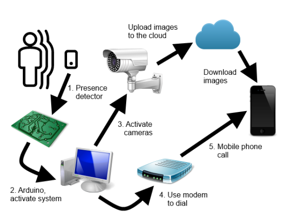
Are you concerned about the security of your home? Do you want to stay one step ahead of potential intruders? In this tutorial, we'll guide you through the process of creating a DIY surveillance system called EaseWatcher that detects unwanted visitors, captures their images, and sends notifications to your mobile device. With this system, you'll be able to respond quickly and provide authorities with valuable evidence to aid in their investigation.
To build EaseWatcher, you'll need some basic hardware components, but don't worry - we've kept costs low by using affordable materials. The cameras are the most significant investment, but they offer a wide range of possibilities, making them a worthwhile addition to your DIY project.
Let's take a look at the system architecture, which consists of several interconnected elements:
While the diagram shows specific subsystems, we've designed the solution to be modular, allowing each component to be developed independently. This is achieved through the implementation of a common interface and dependency injection, which links each element to the application. The subsystems and protocols involved are:
Camera interface: defines communication with video cameras
Storage interface: handles file transfer, image storage, and control commands
Trigger interface: activates the surveillance system
Alarm interface: remotely notifies users of incidents
We've built this solution using Visual Studio 2015 and.NET Framework 4.5.
Please note that due to file size limitations, we've had to remove some files from the source code, including NuGet packages, obj directories, and binaries. While you can restore packages through Visual Studio, you may encounter issues with recompiling the code. If that's the case, you can download the complete project files from our website.
Hardware Components: A Flexible Approach
When building the EaseWatcher system, I used a combination of hardware components that can be easily adapted or replaced to suit your specific needs. In this section, we'll explore the hardware I used in my implementation, but feel free to experiment with different options to create your own customized setup.
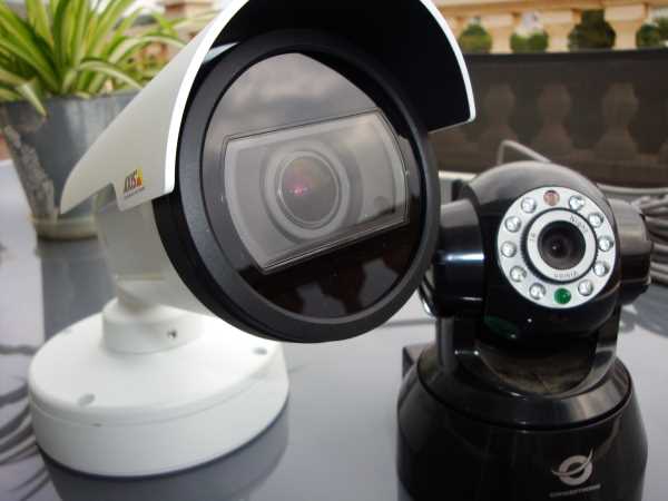
Cameras: The Eyes of the System
I employed two IP cameras, each with its own protocol. The more affordable option was a Conceptornic Wi-Fi camera, priced around €50, which uses the NetWave CGI protocol. The second camera, an Axis model, is a high-performance device with a higher price tag, utilizing the VAPIX CGI protocol.
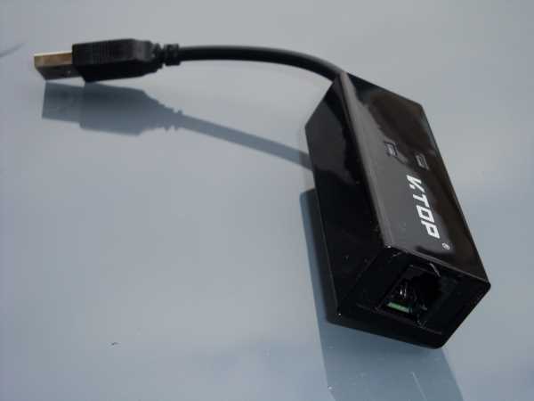
Mobile Notification: A Simple AT Modem
To enable mobile notifications, I opted for a basic USB AT modem, which cost around €17. This device allows the system to send alerts to your mobile phone in case of an incident.
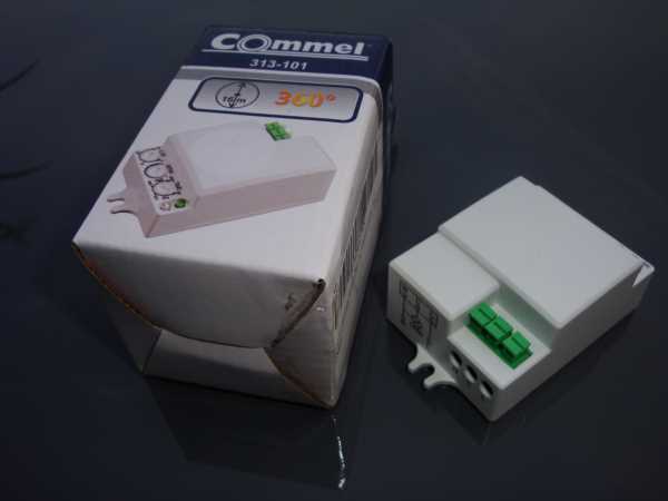
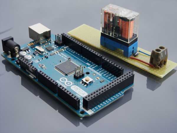
Triggering the System: Arduino and Sensors
For the trigger mechanism, I used an Arduino Mega board (around €20), a presence detector switch (around €10), and a relay. Since the presence switch operates at 220V, it's essential to isolate the Arduino board from the main power source. I achieved this by connecting the detector to a 12V power source, which in turn powers the relay, acting as a switch that closes a circuit between the 5V Arduino power and an input pin.
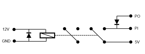
Relay Circuit: A Simple yet Effective Solution
You can easily build a relay circuit like the one I used. Simply connect the 12V power source to the relay reel, add a diode from the ground wire to the 12V wire, and use an input pin (PI) as the trigger pin, an output pin (PO) to force the input pin to 0V when the circuit is open, and the 5V power signal to activate the input pin.
Arduino Code: Pin Configuration
Here's the Arduino code I used, with pin 28 as the input and pin 24 as the output, due to their proximity to the 5V pin on the Arduino Mega board. Feel free to choose alternative pins as needed.
int pin1 = 28;
int pin0 = 24;
void setup() {
// Initialize pins
    pinMode(pin0, OUTPUT);
    digitalWrite(pin0, LOW);
    pinMode(pin1, INPUT);
    digitalWrite(pin1, LOW);
    Serial.begin(9600);
}
void loop() {
    int val = digitalRead(pin1);
    if (val == HIGH) {
        Serial.write(1);
    }
    delay(1000);
}
The Central Control Application
At the heart of the EaseWatcher system lies the control center, a desktop MDI Windows application that orchestrates the entire surveillance process. This application features two primary window types: the control panel and the camera window.
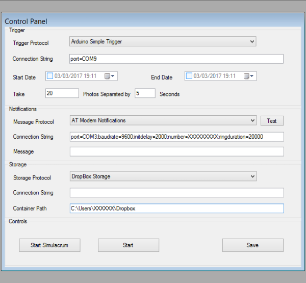
Control Panel
The control panel is where you configure the various protocols, excluding camera settings. The top pane is dedicated to the trigger protocol, allowing you to select the desired protocol, provide a connection string with settings, specify a start and end date/time for surveillance, and configure the number of photos to be taken and the interval between them.
Below this pane, you'll find the notifications (alarm) protocol settings, where you can select a protocol, test it without simulation, and provide a connection string with parameters and an optional message.
The bottom pane is reserved for the storage protocol, where you can set up a connection string, container name, and other parameters as needed.
The command buttons, from left to right, allow you to start or stop the system in simulation mode, start or stop real surveillance, and save changes to the configuration file.
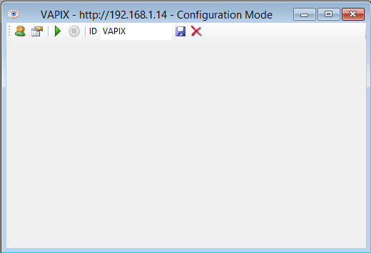
Camera Window
To configure individual cameras, you'll use the camera window, accessible via the File / New Camera... menu option. Here, you'll select the correct camera protocol, provide connection data, camera URL, username, and password. The camera window features a toolbar with buttons to change access settings, show the camera setup dialog box, start and stop the camera, and save or remove the camera configuration.
Configuration Storage
All settings are stored in the application's App.config file, with connection strings in the connectionStrings section and other protocol settings in the appSettings section. Two custom sections, camerasSection and protocolsSection, store camera data and protocol lists, respectively.
The camerasSection contains cameraData elements, each with an id attribute, protocolName attribute, and connectionStringName attribute for connection data.
<camerasSection>
    <cameras>
        <cameraData id="CAMNW"
            protocolName="NetWave IP camera"
            connectionStringName="CAMNW" />
        <cameraData id="VAPIX"
            protocolName="VAPIX IP Camera"
            connectionStringName="VAPIX" />
    </cameras>
</camerasSection>
The protocolsSection lists installed protocols, with each protocolData element featuring a name, class, and type attribute specifying the protocol's implementation.
You can add new protocols to the system using the File / Install Protocol/s... menu option, selecting the class library with the protocol implementation.
Mobile Clients for Remote Monitoring
To ensure that you receive instant notifications of potential intrusions, regardless of your location, I developed mobile apps for the EaseWatcher system. To facilitate rapid development and deployment across multiple platforms, I utilized Xamarin.
The TWClientApp PCL (Portable Class Library) project houses the majority of the client-side code. The platform-specific projects contain minimal code, primarily responsible for saving files and storing images captured by the mobile device's camera, allowing you to swiftly provide evidence to authorities if needed.
As my inaugural mobile app project, it may not be overly complex. I opted not to implement dependency injection, instead focusing on integrating the Dropbox storage protocol. If you wish to utilize an alternative storage solution, you'll need to modify the PCL library code. The Dropbox protocol offers the advantage of allowing users to access images via the Dropbox client, bypassing the ThiefWatcher client (although this approach sacrifices application control capabilities).
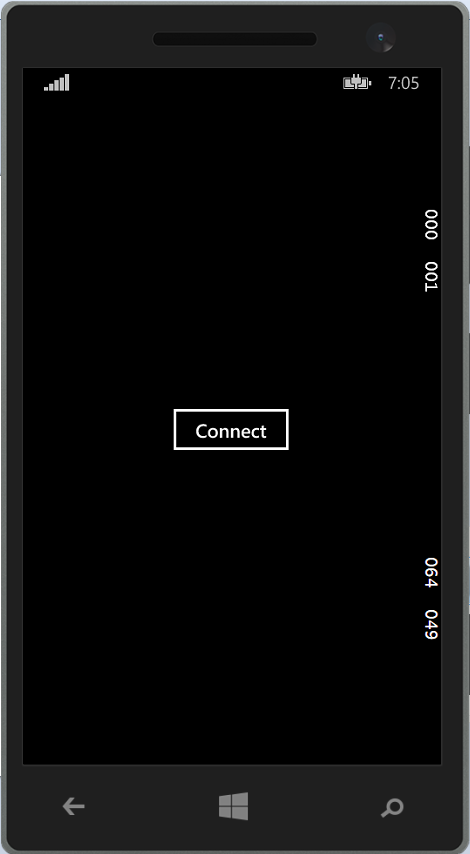
Upon launching the client app, you'll need to press the Connect button to initiate a handshake with the main application:
Connecting to the Main Application
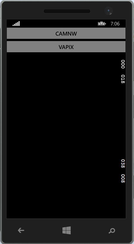
Once connected, a list of available cameras is transmitted to the client. Simply select a camera by pressing the corresponding button:
Camera Selection
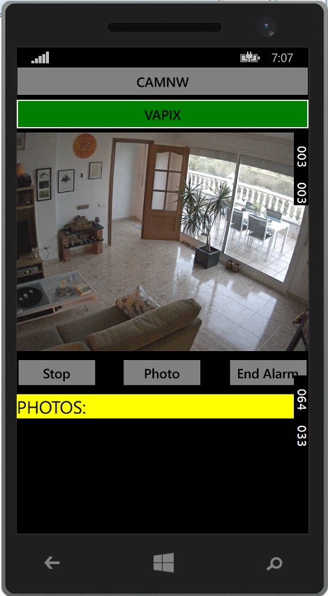
You can then view the current camera feed. Please note that real-time video streaming may not be feasible due to the latency involved in uploading individual images. While the central control system processes frames in real-time, Dropbox may take up to two seconds to upload each image.
Camera Feed
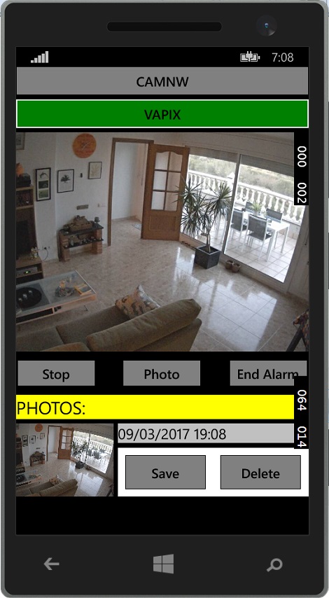
The app provides controls to start/stop camera feeds, capture photos, or terminate alarm mode (no need to stop cameras before ending alarm mode). Captured photos are listed at the bottom of the screen, allowing you to save or delete them as needed.
Photo Management
Although I was unable to test the iOS version due to lack of a Mac environment, the Windows Phone and Android apps function as intended.
Working with the Code
The WatcherCommons project defines various protocol interfaces in the Interfaces namespace. The IWatcherCamera interface, for instance, is responsible for camera interactions and is defined as follows:
This interface provides essential camera functionality, including event handling for new frames, configuration management, and control methods for initializing, starting, and closing camera operations.
The ITrigger interface, used for trigger protocols, is defined as:
This interface enables trigger condition detection, configuration management, and control methods for initializing, starting, and stopping trigger operations.
The IAlarmChannel interface, responsible for notification protocols, is defined as:
This interface provides notification functionality, including configuration management, initialization, and alarm sending.
The protocols implemented in this project include the ATModemProtocol, which utilizes an AT modem to dial phone numbers, and the LyncProtocol, which leverages Skype or Lync for user notification.
The storage protocol, defined in the Data namespace of the WatcherCommons class library, employs two classes: ControlCommand and CameraInfo. These classes facilitate camera command and request interchange in JSON format.
The IStorageManager interface, responsible for storage protocol implementation, is defined as:
This interface provides essential storage functionality, including file management, command and request handling, and response sending.
Two storage protocols have been implemented: the DropBoxProtocol project, which utilizes Dropbox for storage, and a custom storage protocol.
The client-side implementation of the storage protocol is defined in the TWClientApp project and is an asynchronous interface with fewer members than its server-side counterpart.
The client App's code is primarily located in the CameraPage class of the TWClientApp project, which employs a file-based data interchange protocol with specific naming conventions for camera frames, photos, commands, and requests.
In summary, we have explored the various protocol interfaces and implementations that comprise the EaseWatcher system. We have examined the IWatcherCamera interface, which provides camera functionality, the ITrigger interface, which enables trigger condition detection, and the IAlarmChannel interface, which facilitates notification protocols. We have also discussed the storage protocol, which employs the ControlCommand and CameraInfo classes to facilitate camera command and request interchange in JSON format. The IStorageManager interface, responsible for storage protocol implementation, provides essential storage functionality, including file management, command and request handling, and response sending. Two storage protocols have been implemented: the DropBoxProtocol project, which utilizes Dropbox for storage, and a custom storage protocol. The client-side implementation of the storage protocol is defined in the TWClientApp project and is an asynchronous interface with fewer members than its server-side counterpart. By understanding these protocols and interfaces, developers can effectively work with the EaseWatcher system and customize it to meet their specific needs.
For any further details, refer to the download page and download the source code project for reference.
EaseHome is a revolutionary smart home chatbot that lets you control and monitor your home with ease. Using natural language processing and machine learning, EaseHome understands your voice commands and responds accordingly, making it easy to manage your home's temperature, lighting, security, and more. With EaseHome, you can experience the future of smart home automation today.
Welcome to EaseHome: A Smart Home Chatbot Tutorial
Imagine being able to converse with your home, effortlessly asking questions like "What's the current temperature?" or "Are all doors locked?" and even controlling your home's settings with simple voice commands like "Set the kitchen temperature to 19°C!" This futuristic vision, inspired by movies like "Minority Report," is now within reach. In this tutorial, we'll explore how to integrate a cutting-edge text recognition system into a smart home system using the Microsoft Bot Framework and Language Understanding Intelligent Service (LUIS).
The Dream of a Smart Home
The concept of a smart home has long fascinated us. With the advent of voice recognition and text-based interfaces, we can now bring this vision to life. Our goal is to create a seamless interaction between humans and their homes, enabling users to effortlessly control and monitor their living spaces. This tutorial will guide you through the design and implementation of EaseHome, a smart home chatbot that leverages the power of natural language processing and machine learning.
What to Expect
In this comprehensive tutorial, we'll delve into the architecture and design of EaseHome, a Node.js powered bot that utilizes the Microsoft Bot Framework and LUIS. We'll explore the skills and intentions behind our chatbot, configuration management, and the software and hardware mocks used to simulate a smart home system. Additionally, we'll touch on the use of speech-to-text translation systems and provide a bonus section on integrating speech recognition with our chatbot.
To bring our smart home system to life, we'll be using the following components:
Microsoft Bot Framework: A set of tools for building conversational AI interfaces
LUIS: A machine learning-based service for understanding natural language
Node.js: A JavaScript runtime for building scalable server-side applications
ASP.NET Web API: A framework for building web APIs using.NET
Software Mock: A simulated smart home system for testing and development purposes
Hardware Mock (Optional): A CC3200 and/or sensor tags-based hardware setup for a more realistic smart home experience
The Challenge of Building a Smart Home Platform
Creating a secure, reliable, and high-performance smart home platform is a daunting task, especially when considering the vast array of devices and use cases involved. Fortunately, commercial systems like RWE SmartHome have already tackled these challenges, providing a solid foundation for our project.
RWE SmartHome: A Comprehensive Solution
RWE SmartHome, a market leader in Germany, offers a secure and feature-rich platform that covers a wide range of devices and services. At the heart of this system lies the SmartHome Controller (SHC), a central unit that acts as a gateway for all integrated devices. The SHC connects devices, manages rules, and triggers actions when programmed conditions are met. Our bot service will interact with the SHC to read device states and send commands, using the same interface as standard UI clients.
RWE SmartHome Portfolio: A Broad Range of Devices
The RWE SmartHome portfolio includes a variety of core devices, such as radiator thermostats, window door sensors, pluggable switches, and motion detectors. These devices not only provide valuable information about their states (e.g., temperature, humidity, and door/window status) but also offer control capabilities, like adjusting room temperature and controlling lighting. With these devices, the possibilities for automation and monitoring seem endless.
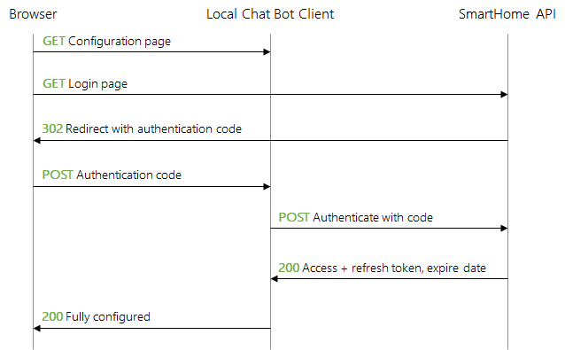
Communicating with the RWE SmartHome Gateway
To interact with the RWE SmartHome system, we need to communicate with the backend operated by RWE. This is achieved through a RESTful web API, which uses OAuth 2 for authentication. By registering a client, we can access the API and utilize its WebSocket channel to listen for events. For the purposes of this article, we'll focus on passive actions, responding to requests without initiating active actions or notifications about state changes.
Designing the Smart Home Chatbot System
Now that we have a solid understanding of the RWE SmartHome solution, let's dive into the architecture and implementation of our smart home bot system. We'll start with a high-level overview and then drill down into the details of each component.
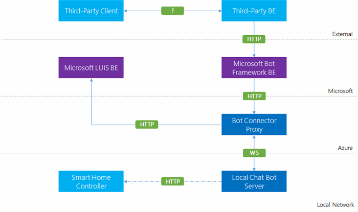
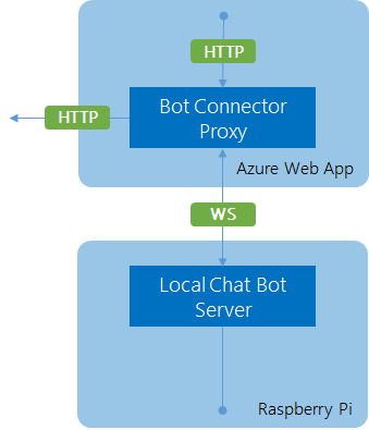
High-Level Architecture
Our architecture consists of a local chatbot client running on a Raspberry Pi, connected to a central bot connector proxy hosted in Microsoft Azure via a WebSocket channel. The bot connector proxy provides a callback endpoint for the Microsoft Bot Connector and a channel registration endpoint for the local chatbot client. The local chatbot client is also connected to the RWE SmartHome system and hosts a small web server for configuration management.
The diagram below illustrates the high-level architecture of our solution, with purple components supplied by Microsoft, light blue components from third-party providers, and our custom components in darker blue.
We'll focus on the two custom components: the proxy and the local chatbot client. The proxy offers an endpoint for Bot Framework callbacks and another endpoint for establishing WebSocket connections with local chatbot clients. It also uses HTTP to query LUIS. The local chatbot client connects to the proxy via WebSocket and uses an internal interface to gather information about the home.
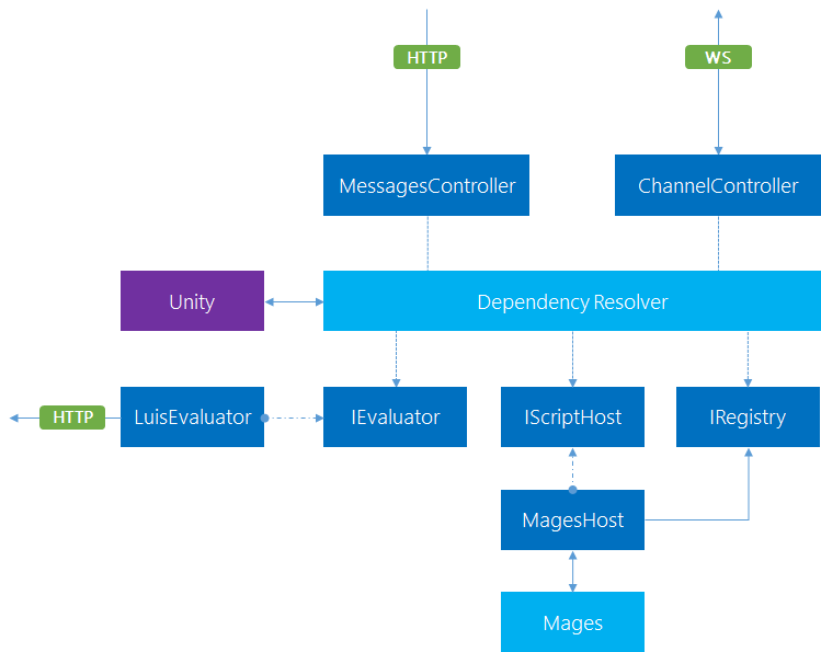
Proxy Architecture
The proxy consists of two endpoints: the messages controller and the LUIS evaluation controller. The messages controller acts as a callback for the Microsoft Bot Connector, receiving messages and determining what to do with them. The LUIS evaluation controller evaluates the message using LUIS to determine the intent and entities.
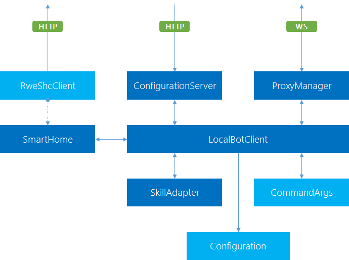
Local Chatbot Client Architecture
The local chatbot client centers around the bot client, which starts all components after reading the configuration. The components are wired together indirectly via events, allowing for loose coupling and easier testing. The most important flow is using the SmartHome component triggered by the ProxyManager in conjunction with the skill adapter, which maps intents to actions using the interface provided by the SmartHome component.
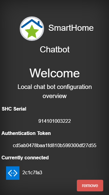
Additional Features
The local chatbot client also runs a web server for quick information and configuration management, and includes a command-line parser for flexibility in starting the application with different configurations or verbosity levels.
Microsoft Bot Framework and LUIS
In this section, we'll delve deeper into the Microsoft Bot Framework and LUIS, which are key components of our smart home chatbot system.
Proxy Implementation
Our proxy is written in C# using the ASP.NET Web API framework and the Microsoft Bot Builder library. The /api/messages endpoint reacts to POST requests by calling the following action. The body of the request is serialized as an Activity instance.
public async Task<HttpResponseMessage> Post([FromBody]Activity activity)
{
    if (activity.Type == ActivityTypes.Message)
    {
        /*... see below... */
    }
    else
    {
        SystemMessageHandlers.Handle(activity);
    }

    return Request.CreateResponse(HttpStatusCode.OK);
}
Handling System Messages
System messages are handled generically using the SystemMessageHandlers class.
For user messages, we need to evaluate the message using LUIS to determine the intent and entities.
var serviceUrl = new Uri(activity.ServiceUrl);
var connector = new ConnectorClient(serviceUrl);
var connection = _registry.GetFor(activity.ChannelId, activity.From.Id);

if (connection!= null)
{
    await AskQuestionAsync(activity, serviceUrl, connection);
}
else
{
    await TryRegisterAsync(activity, connector);
}
LUIS Evaluation
The AskQuestionAsync method uses an instance of IEvaluator to perform the evaluation of the message. The result is then sent to the connection that has been retrieved previously.
public async Task<String> EvaluateAsync(String input)
{
    var query = Uri.EscapeDataString(input);

    using (var client = new HttpClient())
    {
        var uri = $"https://api.projectoxford.ai/luis/v1/application?id={ApplicationId}&subscription-key={SubscriptionId}&q={query}";
        var msg = await client.GetAsync(uri);

        if (msg.IsSuccessStatusCode)
        {
            return await msg.Content.ReadAsStringAsync();
        }
    }

    return null;
}
LUIS Project Definition
The LUIS project definition is a JSON file that contains all the information that represents our model. For the source code attached to this article, it is sufficient to illustrate the most simple model consisting of a single intent with an optional entity.
The general tendency is to increase the accuracy by providing more utterances. Nevertheless, as we increase the number of intents, the utterances needed to keep the accuracy stable will increase exponentially.
Skills: Combining Intentions and Entities
The skill adapter is a crucial component that maps intents to JavaScript modules and calls the function exported from the module with the smart home adapter and the given entities. This allows us to handle queries from the proxy to the client in a flexible and modular way.
Skill Adapter Implementation
The skill adapter is a simple class that requires a smart home adapter to be created. The resolution of skills takes place in the resolve method, which looks for JavaScript files in the skills subfolder that match the name of the given intent.
Here is an example of a skill that retrieves the temperature from the smart home adapter. The get-temperature skill uses the smart home adapter to retrieve all temperature states asynchronously. Once the values are known, it filters the result set based on the entities provided.
The best thing about skills is that they can be extended or improved during runtime, allowing the system to evolve as more intents are modeled. This is great for prototyping or for an update process that is to be defined later.
Configuration Management
To simplify development, a configuration management system has been established that is both simple and flexible. The system aggregates all important settings in a single JSON file and allows for specialization of these settings in another file. The primary file is always loaded, while the specialized file is only loaded upon request (i.e., if a file with the given name exists). Settings in the specialized file override or extend the settings in the primary file.
Environment Specialization
The specialization is called an environment. The primary settings file is the global file, while the specialized file is the environment (or local) file. The environment file follows the naming convention of having a file name without extension that ends with .environmentname, where environmentname represents the chosen environment name. For development, two specializations have been used: debug and release (reasonable and familiar choices).
Global and Environment Files
The global file contains generic settings, while the environment file contains specialized settings that override or extend the global settings. For example, the global file might contain:
While the environment file for the debug environment might contain:
{
  "adapter": {
    "host": "localhost:3979"
  }
}
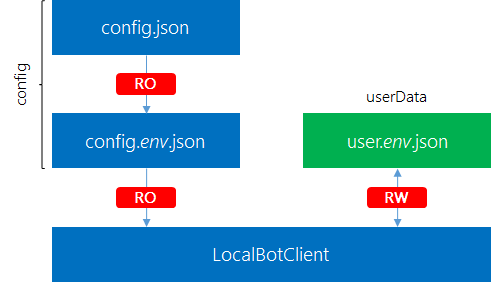
User Configuration
A local chat bot client is mapped to a single user by definition. The user may have different accounts registered in different channels (e.g., Skype, Slack,...). The userData file is bound to an environment, as different environments may use different connection URLs and smart home credentials. Therefore, it makes sense to specialize the user configuration with the given environment.
Hierarchical Configuration vs. User Data
The configuration is read-only and never modified by the application, while the user data is populated exclusively by the application. The user data file is used to store persistent information about the user, which is used to continue with the previous state on application restart. This file also stores the refresh token (see OAuth 2 flow) required to get an access token for the smart home system.
Security Considerations
Storing the refresh token unencrypted is a security risk. For a client that will be deployed, the refresh token should never be stored in an unencrypted fashion.
Web Server Configuration
The web server is configured using a wrapper class that provides loose coupling between the rest of the application and the web server. The routes are part of this abstraction layer. The WebServer class is used to render the JADE view engine.
This concludes the configuration management in our chat bot.
Getting Started with the Code
The code we've developed so far is designed to be usable from the start, but we also recognize that you may need to switch to a different smart home provider in the future. To accommodate this, our solution doesn't come bundled with a specific provider, such as RWE SmartHome. Instead, we've included a generic software provider and two hardware providers that you can use.
The choice of provider is entirely up to you. We've designed the system to be highly configurable, making it easy to switch between providers or even create your own custom provider. This flexibility also means that you can integrate your custom provider with an existing home automation system or any other tool of your choice.
To get started, you'll need to configure the system by supplying the required parameters.
Bot Connector Proxy Setup
The bot connector proxy is an ASP.NET Web API project. To deploy or test the solution, you'll need to update the web.config file with the required parameters. The file should look like this:
Fill in the required fields for deployment, or provide at least the LuisApplicationId and LuisSubscriptionId values for testing.
The Software Mock
Any smart home adapter must implement the SmartHomeAdapter interface, which includes methods for refreshing, logging in, and retrieving device states. Our software mock should be simple, flexible, and suitable for unit testing and integration with other hardware.
To make the mock more useful, we can add configuration options to transport predefined sets of devices, locations, and capabilities. We can also use a module to load data from local files, making it easier to integrate with hardware.
Building a Resolver
A key function in our software mock is the buildResolver function, which creates a resolver from a given function or entities. This function is used in the constructor to resolve devices, locations, and capabilities.
This function is used to create resolvers for devices, locations, and capabilities, making it easy to customize the behavior of the software mock.
Helper Functions
To make it easier to work with the software mock, we've also included some helpful functions for reading files and parsing JSON data. These functions can be used to quickly load data from local files and integrate with hardware.
function readLinesFromFile(fn) {
  const data = fs.readFileSync(fn, 'utf8');
  return data.trim().split('\n');
}

function readLastLineFromFile(fn) {
  const lines = readLinesFromFile(fn);
  return lines.slice(-1)[0];
}

function readFileAsJson(fn) {
  const data = fs.readFileSync(fn, 'utf8');
  return JSON.parse(data);
}
With these helper functions and the software mock in place, you're ready to start building your smart home solution with EaseHome.
Using a Single CC3200 Instance
While the software mock is a great way to experiment with the smart home chatbot solution, eventually, we'll want to connect it to real sensors. However, we may not want to invest in a comprehensive smart home system like RWE SmartHome, especially if it's not available in our region or doesn't provide an API. In such cases, a lightweight solution like the CC3200 microcontroller unit (MCU) can be a suitable substitute.
The CC3200 is a powerful MCU that comes with a development board called the CC3200-LaunchXL. This board is equipped with extension possibilities and integrated sensors, including a temperature sensor, making it an ideal choice for our project.
In this section, we'll guide you through the necessary steps to set up a CC3200 development board and program it to read sensor data and periodically send it to a local server, where the chatbot is running.
Requirements
To use a CC3200 for obtaining sensor data, you'll need:
The TI CC3200-LaunchXL board
A USB micro cable
The Energia IDE installed
Internet access via WiFi for the CC3200
A code editor of your choice (e.g., Energia, Sublime Text, Emacs, or vim)
Connecting the LaunchPad
To get started with the LaunchPad, simply press CTRL + M in Energia. This will compile the binaries, upload the code, open the serial monitor, and run the application. However, the LaunchPad's design makes it less than ideal for a quick build-test-debug loop. You'll need to set different jumpers to switch between run-mode and program-mode.
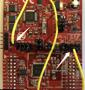
Here's a neat workaround using the J8 (TOP) connector and the SOP2 (BOTTOM) connector:
By following these steps, you can simplify the process:
Remove both jumpers J8 and SOP2 (if installed).
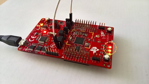
Connect one side of the jumper wire to the top of J8 and the other side to the bottom of SOP2.
Run the code from Energia via CTRL + M. You should see the serial monitor pop up (make sure to configure the correct baud rate!) and the LEDs start blinking.
Now that we have our setup working, let's take it to the next level. We can either use one of the buttons (PUSH1 or PUSH2) or leverage an integrated sensor. For the buttons, we'd use digitalRead to get the state (HIGH or LOW) and constantly monitor the current state via polling. But let's skip the buttons and dive straight into using sensor input.
Making HTTP Requests
We've made significant progress so far, from a simple "Hello World" to gathering sensor information and triggering outputs based on that data. Now, we're ready to take the critical step of adding wireless connectivity to the world wide web, enabling IoT applications.
To demonstrate this, we'll use httpbin.org to make an HTTP request to its API, retrieve a single integer, and display the result using a blinking LED. We'll also insert a five-second pause (LED off) after each HTTP call.
Establishing a Network Connection
Before we can make an HTTP call, we need to establish a network connection. Fortunately, the CC3200 LaunchPad comes with a WiFi chip on-board. We'll create a new file, wifi.cpp, to handle the WiFi connection.
The header file is simple, declaring a single function:
#pragma once

void connectWifi(char* ssid, char* password);
The source file contains print statements for debugging and uses the WiFi library that comes with Energia:
#include "wifi.h"
#include <Energia.h>
#include <WiFi.h>

void connectWifi(char* ssid, char* password) {
  Serial.print("Connecting to WIFI network ");
  Serial.print(ssid);
  WiFi.begin(ssid, password);

  while (WiFi.status()!= WL_CONNECTED) {
    Serial.print(".");
    delay(300);
  }

  Serial.println(" connected!");
  Serial.print("Waiting for an IP address ");

  while (WiFi.localIP() == INADDR_NONE) {
    Serial.print(".");
    delay(300);
  }

  Serial.println(" received!");
}
The code establishes a WiFi connection, waits for the connection to be established, and then waits for the router to assign an IP address.
Making an HTTP Request
Now that we have a WiFi connection, we can make an HTTP request. We'll create a new function, httpGetRequest, to handle this:
bool httpGetRequest(char* hostname, char* path);
The function takes a hostname (e.g., httpbin.org) and a path (e.g., /bytes/4) as input. The source code for the function is:
The function defines the request message to send, retrieves the IP address of the host, sets up the connection socket, and sends the request. The response is received as a single string, which needs to be parsed to extract the desired information.
When we run this code, we should see a response similar to:
The last characters are the string representation of the 4 random bytes we're interested in. Note that a random binary byte may not correspond to a printable ASCII symbol.
Playing with the LaunchPad
Debugging software on embedded systems like the CC3200 LaunchPad can be a challenging task. Unlike traditional programming, we don't have access to the same tooling and techniques we're familiar with. However, there are still ways to gain insights into what's happening on the device.
One useful utility is the Serial class, which allows us to print messages to the serial interface and gain some understanding of the system's behavior. The CC3200 LaunchPad also features a JTAG (4-wire) and SWD (2-wire) interface for development and debugging, but we won't be exploring those in this tutorial.
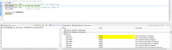
Instead, we'll focus on using the serial interface provided by the FTDI connector via USB. We've already seen how writing messages to the serial interface can be helpful, but an even more powerful approach is to use the Code Composer Studio (CCS) from Texas Instruments. CCS allows us to set breakpoints, which is a much more efficient and effective way to debug our code.
To get started with CCS, we'll need to download and install it, then set it up to connect to the correct COM port with the configured bandwidth. It's also important to configure CCS to point to the Energia installation path, otherwise, it may not be able to find the required libraries and files. Once we've done that, we can open Energia projects directly from CCS.
One of the cool features of CCS is its ability to view the currently used registers and memory directly. This can be a huge help in tracking down errors in our code.
With CCS, we can accelerate our search for errors and get back to solving our original problem: making a secure HTTP request from the CC3200.
Digging Into the Accelerometer
The CC3200 LaunchPad comes equipped with several sensors, including a temperature sensor (tmp006) at address 0x41 and an accelerometer (bma222) at address 0x18. In this example, we'll focus on using the accelerometer, which is easier to work with for demo purposes.
Important Note
Due to an overlap in the address register, we can't use the yellow and green LEDs together with the accelerometer. Therefore, we'll only use the red LED from now on.
To read the accelerometer sensor, we'll include the Wire.h header and create a new file called accelerometer.cpp with a corresponding header file accelerometer.h. Our initial code looks like this:
The readAccelerometer function is declared in our new header file. In the setup function, we need to initialize the Wire library. In each iteration, we read the accelerometer and print the values to the screen.
The AccData structure is defined in our header file as follows:
Each read operation starts an I2C connection to the device at the given address. We use the Wire library to abstract away the low-level I2C communication protocol.
Now that we have the accelerometer data, we can modify the code in the loop function to show the red light when the board is "falling". From our elementary physics course, we know that a free-falling body is essentially force-free, meaning the acceleration in the z-direction will be zero (compared to 1g for a body standing on the earth's surface). We assume the z-axis of the accelerometer is pointing upwards.
We measure a value of approximately 65 in the z-direction by default, so we can normalize to this value. We'll show a red light for values below 0.4g, i.e., when the value drops below 26. Our modified code looks like this:
The red LED will light up for at least 1 second once triggered.
Reading and Sending the Temperature
To receive and store the temperature data, we can set up a simple Node.js express server (e.g., listening on port 3000). The server code can be as follows:
const express = require('express');
const app = express();

app.use((req, res, next) => {
      req.rawBody = '';
        req.setEncoding('utf8');

          req.on('data', (chunk) => {
                  req.rawBody += chunk;
                    });

            req.on('end', () => {
                    next();
                      });
});

app.post('/temperature', (req, res) => {
      console.log(req.rawBody);
        // Process the raw value as needed
          res.send('');
});

app.listen(3000);
With our previously established helpers in place, we can write concise and functional code for the CC3200.
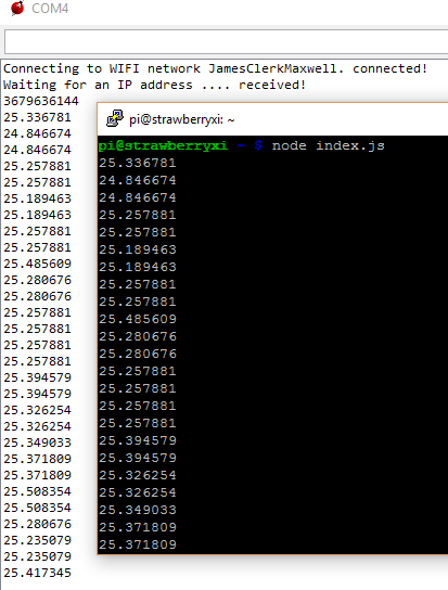
The following code connects to the local WiFi, initializes the temperature sensor, and continuously reads the sensor data with a 2-second interval (for illustration purposes).
By following these steps, we can successfully read and transport the temperature data. Let's verify this using the debugger.
Expanding Sensor Capabilities with Multiple Tags
When a single CC3200 is not sufficient, we can leverage multiple temperature sensors connected via Bluetooth Low Energy (BLE). This approach can be more straightforward than using the CC3200, which requires low-level hardware details to read sensor data and perform HTTP requests on a minimal operating system.
SensorTag and Raspberry Pi Integration
We can utilize a TI SensorTag with a Raspberry Pi 3 to retrieve temperature readings via BLE.
Prerequisites
To fully integrate this approach into our setup, we need:
An active Bluetooth connection on the Raspberry Pi
At least one TI SensorTag
A text editor installed on the Raspberry Pi 3, such as nano, ed, or vim
The Raspbian Jessie image on the Raspberry Pi 3, which comes with Bluetooth drivers (otherwise, run sudo apt-get install pi-bluetooth)
Configuring the Hardware Environment
We begin by setting up the hardware environment. The software should be pre-configured, especially if we choose to use one of the available images.
Exploring Bluetooth from the Command Line
We connect to the Raspberry Pi using our favorite SSH client (e.g., Putty on Windows). In the shell, we can explore the TI SensorTag using the following instructions:
Run the standard Bluetooth program by typing bluetoothctl.
Enable Bluetooth if it's not already on by typing power on. Similarly, disable Bluetooth with power off.
Use the devices command to list paired devices.
Enter device discovery mode with scan on. After some time, the sensor tag should appear (e.g., with MAC address 34:B1:F7:D4:F2:CF).
Enter pair 34:B1:F7:D4:F2:CF to create the pairing between the Pi and the sensor tag.
Stop discovering devices with scan off.
Exit the program by typing quit.
This way, we've discovered and paired our device. Now we can use gatttool to interact with the sensor tag.
Interacting with the Sensor Tag using Gatttool
Run the program by typing gatttool -b 34:B1:F7:D4:F2:CF --interactive. We enter an interactive session.
The first command we issue is connect. We should see a "Connection successful" message.
Now we can attempt to read from the sensor tag: char-read-hnd 0x25 uses the handle 0x25 to read data from the thermometer. We should see some zeros.
To read some values, we need to enable the thermometer. We issue char-write-cmd 0x29 01 to turn the thermometer sensor at 0x29 on.
Issuing the command char-read-hnd 0x25 again should now yield a non-zero value.
Exit the program by typing quit.
Sensor Handles
The TI SensorTag comes equipped with a variety of sensors, including:
Contactless IR temperature sensor (Texas Instruments TMP006)
Humidity sensor (Sensirion SHT21)
Gyroscope (Invensense IMU-3000)
Accelerometer (Kionix KXTJ9)
Magnetometer (Freescale MAG3110)
Barometric pressure sensor (Epcos T5400)
On-chip temperature sensor (Built into the CC2541)
Battery/voltage sensor (Built into the CC2541)
Each sensor has its own unique handle, which is used to interact with it. The following table provides a brief overview of some of the sensors and their corresponding handles:
Sensor
Read Handle
Length
Configure Handle
Data Handle
IR Temperature
0x25
4 bytes
0x29
0x26
Accelerometer
0x2d
3 bytes
0x31
0x2e
Humidity
0x38
4 bytes
0x3c
0x39
Magnetometer
0x40
6 bytes
0x44
0x41
Barometric Pressure
0x4b
4 bytes
0x4f
0x4c
Gyroscope
0x57
6 bytes
0x5b
0x58
The barometric pressure sensor requires an extra calibration step, which must be performed before taking the first measurement. This involves issuing the command char-write-cmd 0x4f 02 to perform the calibration, and then reading the raw value using char-read-hnd 0x52.
The following image shows a detailed map of the sensor components on the SensorTag board.
SensorTag Hardware
With this information, we can now write a simple bash script to query the sensors at regular intervals and write the results to a text file. This script can be used to pair devices, read sensor values, and perform other tasks.
For example, the following script pairs all devices listed in a file called devices.
#!/bin/bash

bluetoothctl <<< "power on"
sleep 1s
bluetoothctl <<< "scan on"
sleep 5s

while IFS='' read -r line || [[ -n "$line" ]]; do
  bluetoothctl <<< "pair ${line}"
done < devices

sleep 4s

while IFS='' read -r line || [[ -n "$line" ]]; do
  bluetoothctl <<< "disconnect ${line}"
done < devices
We can use a similar script to read temperature sensor values from these devices.
#!/bin/bash

while IFS='' read -r line || [[ -n "$line" ]]; do
  gatttool -b ${line} --char-write -a 0x29 -n 01
  gatttool -b ${line} --char-read -a 0x25
done < devices
From here, it's easy to continue polling the device at regular intervals (e.g., every five minutes) to gather information about the temperature.
Unlocking the Power of Speech-to-Text
Once we have established a robust text layer, the possibilities for innovation are endless. One of the most exciting opportunities is to integrate a speech-to-text layer on top of our design. While some clients, such as Skype on mobile platforms, offer this functionality for free, we may want to create a custom application that provides voice recognition as an input option.
Integrating with Direct Line
To integrate a speech-to-text client with our chatbot system, we can utilize a direct line. By leveraging the Microsoft.Bot.Connector.DirectLine package from NuGet, we can create a custom channel that interacts with our chatbot API.
The following code demonstrates how to get started with creating our own chat client:
sealed class MessageChannel : IDisposable
{
    private static readonly string BingSecret = ConfigurationManager.AppSettings["BingSecret"];
    private static readonly string EndPoint = ConfigurationManager.AppSettings["SmartBotEndpoint"];
    private static readonly Uri DirectLine = new Uri("https://directline.botframework.com");

    private readonly Conversation _conversation;
    private readonly DirectLineClient _client;

    public event EventHandler<MessageEvent> Received;

    public MessageChannel()
    {
        var credentials = new DirectLineClientCredentials(BingSecret, EndPoint);
        _client = new DirectLineClient(DirectLine, credentials);
        _conversation = _client.Conversations.NewConversation();
    }

    public Task SendAsync(string content)
    {
        var message = new Message(text: content);
        return _client.Conversations.PostMessageAsync(_conversation.ConversationId, message);
    }

    public async Task ReceiveAsync(CancellationToken cancellationToken)
    {
        var watermark = default(string);

        while (!cancellationToken.IsCancellationRequested)
        {
            var messages = await _client.Conversations.GetMessagesAsync(_conversation.ConversationId, watermark, cancellationToken);

            foreach (var message in messages.Messages)
            {
                Received?.Invoke(this, new MessageEvent(message.Text, message.Created, message.FromProperty));
            }

            watermark = messages.Watermark;
        }
    }

    public void Dispose()
    {
        _client.Dispose();
    }
}
The SendAsync method posts a single message to the conversation, while the ReceiveAsync method retrieves messages from the conversation, including those sent by our chatbot. By using a watermark, we can retrieve only the new messages since the last retrieval, effectively implementing a long polling mechanism. The received messages are then delivered as events.
Bing Speech-To-Text Integration
One of the simplest ways to incorporate speech recognition into a C# application is by utilizing the Bing Speech-To-Text API. We can leverage the Microsoft.ProjectOxford.SpeechRecognition-x64 package, available on NuGet, to create a VoiceChannel class that enables microphone input.
The beauty of this library lies in its simplicity. All we need to do is create a new client using the SpeechRecognitionServiceFactory factory. In our case, we want to utilize the Bing Speech-To-Text service and integrate it with our defined model, which is currently residing in LUIS. Therefore, we use the CreateMicrophoneClientWithIntent method. Besides the obvious Bing subscription, we also need to supply our LUIS application and subscription ID. The rest is handled internally.
The library even takes care of finding and controlling the microphone, including recording and other tasks. A few events make the library smooth and easy to work with.
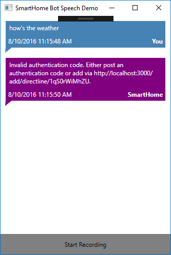
With speech recognition available, we can easily wire everything together. In the end, the UI can be as simple as having a button to start and end the speech recognition, and a message dialog to display all the performed questions and answers.
Additionally, we may also want to integrate speech output, which can be done using the System.Speech library (deployed with Windows 8+ and.NET 4.5).
Text-to-Speech Synthesis
Utilizing a speech synthesizer is a cost-effective and reliable way to provide basic audio output, which can be particularly useful for enhancing accessibility. While accessibility is not the primary focus of our scenario, we can leverage this technology to create a cool and engaging experience.
The following code implements a simple text-to-speech synthesizer. Note that the class is a minimal wrapper, and the SpeakAsync method does not return a Task. To determine when the message has finished playing, we need to check the IsCompleted property of the returned prompt. For brevity, we have kept the implementation simple and minimal, omitting additional logic such as message queuing.
sealed class SpeechChannel : IDisposable
{
    private readonly SpeechSynthesizer _synthesizer;

    public SpeechChannel()
    {
        _synthesizer = new SpeechSynthesizer();
    }

    public void Dispose()
    {
        _synthesizer.Dispose();
    }

    public void Say(string message)
    {
        _synthesizer.SpeakAsync(message);
    }
}
The screenshot below shows the final result, a lightweight WPF application that consists of an item control and a button. The messages are received continuously, providing a seamless user experience.
Configuring the Speech Client
To utilize the speech client, we need to provide some essential configuration settings. These settings are stored in the app.config file of the provided source code.
The following XML snippet highlights the fields that require input:
<?xml version="1.0" encoding="utf-8"?>
<configuration>
  <appSettings>
    <add key="LuisApplicationId" value="/* Enter Your LUIS Application ID here */" />
    <add key="LuisSubscriptionId" value="/* Enter Your LUIS Subscription ID here */" />
    <add key="SpeechLocale" value="en-US" />
    <add key="BingPrimaryKey" value="/* Enter Your Bing Speech-To-Text Primary Key ID here */" />
    <add key="BingSecondaryKey" value="/* Enter Your Bing Speech-To-Text Secondary Key ID here */" />
    <add key="DirectLineSecret" value="/* Enter Your Direct Line Secret here */" />
    <add key="SmartBotEndpoint" value="/* Enter Your Chat Bot API Endpoint here */" />
  </appSettings>
  <!--... -->
</configuration>
In addition to the LUIS subscription, which provides the Bing Speech-To-Text service with more information and a model for resolution, we also require a Bing Speech-To-Text subscription, currently available as a preview. We can obtain the primary and secondary key from the Bing Speech-To-Text webpage. Furthermore, we need to provide the secret for the direct line connection, which ensures that our client is authorized to communicate with our bot adapter.
Expanding the System's Capabilities
The system's flexibility allows for seamless integration with other home automation facilities, making it a versatile tool for managing various aspects of one's life. I have personally extended the system to monitor server infrastructure and multimedia offerings, freeing myself from the need for platform-specific apps. With the chatbot at my fingertips, I can simply send messages like "pause the current movie" or "increase the volume by 5%" to control my devices.
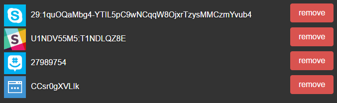
Adding new intents to the system is a straightforward process, making it easy to expand its capabilities. Currently, I have three channels permanently connected to my bot, with the web chat serving as a fourth channel, as shown in the screenshot below.
The system allows for connections via multiple channels, including Skype, Slack, and GroupMe, providing users with flexibility and convenience. While each channel is distinct, we could potentially store conversation-specific logic on the local chatbot client, enabling us to break conversation boundaries and leverage information from one channel to answer questions in another. However, this approach may introduce complexity and confusion for users, so it's not a priority at this time.
A brief GIF video demonstrates the basic interaction with the bot via Skype.