Create a custom smart lock device for your existing door that integrates an Atmega328 microcontroller, HC-05 Bluetooth module, and relay module, enabling remote operation from any paired Android device.
In this project, We will show you how to build a comprehensive prototype of smart lock step by step with minimal cost.
The initial intent with this tutorial was to show you that you can make build this project even if you have little experience with all of the various parts (AVR chips, Bluetooth, Android). We still believe you can if you follow the steps in this tutorial.
Getting Started
Create a custom smart lock device for your existing door that integrates an Atmega328 microcontroller, HC-05 Bluetooth module, and relay module, enabling remote operation from any paired Android device.
In this project, I will show you how to build a comprehensive prototype of smart lock step by step with minimal cost.
Introduction
Developing a product that goes beyond software requires mastering multiple technologies, which can be a daunting task. However, this diversity can also be the most fascinating aspect of the project.
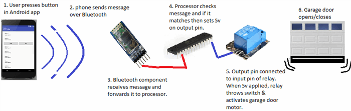
Below is a rough diagram that provides a comprehensive overview of the project. It illustrates all the necessary components and should give you a general understanding of how this system functions.
In general, this project allows to open your door via Bluetooth.
Components Summary
Essential Hardware Components for the Project:
- Bluetooth module (HC-05) - A wireless Bluetooth serial transceiver module for seamless connectivity
- Microcontroller: ATMega328P - A powerful AVR chip with Arduino UNO bootloader, available on Amazon
- Relay module - A 5V relay module compatible with official Arduino boards, ideal for switching applications
- Breadboard - A 3x solderless breadboard with 400 tie-points for easy circuit prototyping Assorted jumper wires for connections
- LED indicator for power status
- 220 Ohm resistor for LED circuit
- 22 pF disc capacitor for power filtering
- 5V power adapter/transformer with 850mA output, repurposed from an old Motorola Razr charger or available on Amazon"
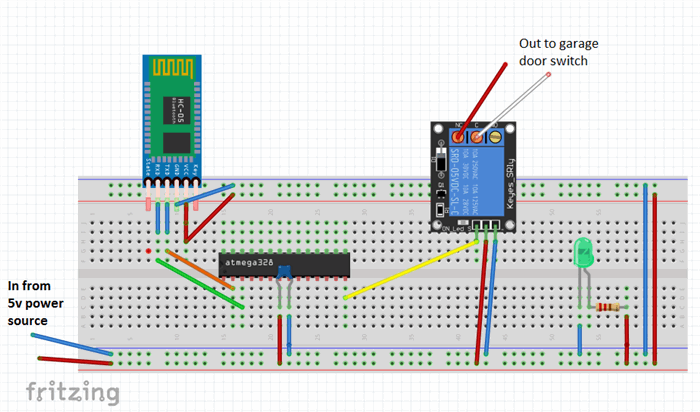
Fritzing Circuit
If you're familiar with the excellent app from fritzing.org, you know that it allows you to design and simulate your circuit. I've uploaded the completed board's schematic to: http://fritzing.org/projects/bluetooth-garage-door-opener
On the website, you can access the circuit diagram, customize it to suit your needs, and even test it.
As you can see from the final schematic, the electronics involved are surprisingly straightforward to build, and the required components are minimal.
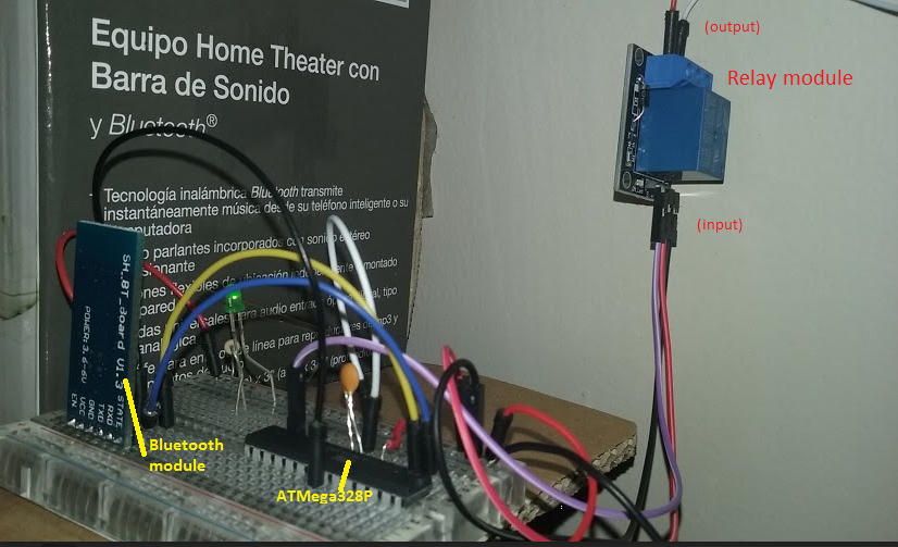
The Prototype
The prototype may still be in its rudimentary state on a breadboard, but it has proven to be a reliable performer, consistently opening many doors without a hitch every day.
Background
Upon moving into a new home, I was surprised to find an antiquated overhead door opener, but to my dismay, there were no wireless remotes included. Typically, a universal remote would suffice, but these old models required original LiftMaster remotes, which were scarce and pricey, with each one costing around $30USD. It's frustrating to be forced to purchase a separate remote at such a steep cost. It seems absurd, considering we all carry devices like phones and tablets that are more than capable of controlling a simple garage door, making the need for a dedicated remote seem redundant.
I Was Determined To Find A Way To Make It Work
As a seasoned software developer since 1995, I was determined to find a more efficient way to control my garage door. Initially, the concept of creating a wireless garage door control seemed daunting, requiring expertise in radio frequency (RF) and related complexities. However, I simplified the problem by focusing on the core requirement: remotely activating a switch.
At its core, a garage door opener is essentially a wall-mounted switch that controls the motor installed on the ceiling. When I press the switch, the motor is activated. Therefore, the fundamental challenge is to either replace the switch or find a way to activate it remotely, while ensuring that the existing wall switch continues to function as usual.
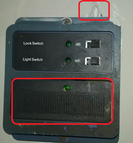
Identifying the Root Cause
I began by examining the switch on my garage wall, which, I must admit, is quite outdated and aesthetically unpleasing. Upon closer inspection, I identified the incoming wires from the garage door motor at the top and the momentary switch at the bottom, which is pressed by the user to open or close the garage door.
A Crucial Hint: Garage Switch Safety
A crucial observation! I took note of the wire gauge, which, as a rough guideline, can indicate the voltage and current it carries. Please keep in mind that this is not professional electrical advice, and I strongly advise against attempting anything that makes you uncertain. Safety first!
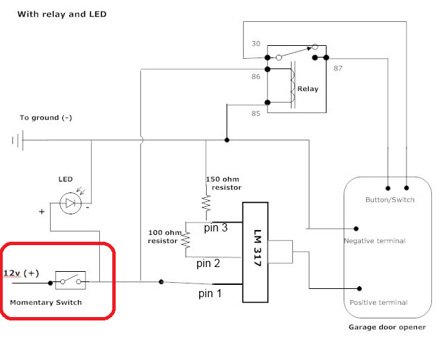
As many of us familiar with garage door openers know, there are usually two thin wires connecting the switch to the motor on the ceiling. This suggests that they likely carry relatively low voltage and current. A quick internet search for "momentary switch garage door" reveals that these wires typically carry around 12 volts.
I stumbled upon a schematic that supports this, specifically a DIY guide on integrating a 3V garage door opener remote to a vehicle, found on the Toyota FJ Cruiser Forum.
First Step Is To Add Two Wires
My first step was to add two wires to extend the circuit to my new remotely controlled switch. I began by removing the switch from the wall and examining the wiring behind it.
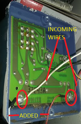
As shown, I can see the incoming wires from the garage door motor, and I added two new wires to the same screws by loosening them, curling the wires around them, and then tightening the screws back down.
After completing the addition and reassembling the panel, it looked like this:
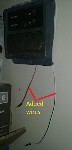
By touching the two wires together, I could activate the garage door motor (GDM), and conversely, if the GDM was already active, touching the wires together would deactivate it.
This step may seem straightforward, but it was a crucial milestone, as it demonstrated that if I could remotely control the connection of these two wires (completing the circuit), I would achieve my goal. What I needed now was an electronically activated switch to facilitate this remote control.
Electronically Activated Switch
Deep within my mind, a faint memory resurfaced - a valuable piece of information I had read in the exceptional book "Code: The Hidden Language of Computer Hardware and Software" by the renowned programming author, Charles Petzold.
Electronic Relay
Petzold also reveals that relays essentially function as switches that are operated by electromagnetic forces, which is exactly what I've been looking for.
How Do Relays Work?
The fundamental principle of a basic relay operates as follows: when a voltage is applied to the primary circuit, it energizes an electromagnet, which in turn attracts a metal armature, switching it from its normally open state to a closed state, thereby establishing a connection in the secondary circuit and allowing electrical current to flow, ultimately activating the device, such as the GDM.
Electromagnetic Coil: Wrapping Around an Iron Core
I'd like to break down the concept of relays in simple terms, so bear with me, electronics experts!
In essence, an electromagnet can be created by wrapping copper wire around a piece of iron, forming a coil. When electricity flows through the wire, a magnetic field is generated. This principle is the foundation of relay creation.
A basic relay consists of a coil and a metal piece that rests in one position and moves to the closed position when voltage is applied to the coil, causing the magnetic field to shift the metal switch.
Here's a simple circuit diagram of a relay, similar to the one I'm referring to:
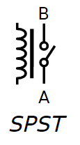
Note that SPST stands for single-pole single-throw, meaning there's a single switch that switches in one direction.
Relay Basics: Keeping it Simple
You're right, creating a functional relay circuit involves more than just the relay itself. Even with modular relay units, additional components like diodes are necessary to ensure proper operation.
To simplify the process, I opted for a complete pre-made relay circuit module. These modules include all the necessary diodes and components to ensure reliable switching. They also provide easy connections for the primary and secondary circuits, making it a convenient and hassle-free solution.
Using a pre-made relay circuit module saved me time and effort, allowing me to focus on the overall project rather than delving into the intricacies of relay circuit design.
Relay Circuit Module: Affordable and User-Friendly
The relay circuit module I used in this project resembles the following:
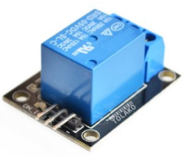
This module is not only inexpensive but also incredibly easy to use, making it perfect for my project.
I purchased the relay module through Amazon, and you can also get yours from there if you're interested: Tolako 5v Relay Module for Arduino.
The large blue box at the center of the circuit board is the actual relay, which consists of a coil that generates a magnetic field, moving the switch. Note that this device is marketed as being "for Arduino" because most people programming AVR ATMega chips use Arduino boards. However, it works perfectly fine with our setup, and the manufacturer could have just as easily marketed it as compatible with AVR chips. The "Arduino" label is likely due to its popularity and buzz.
Output Circuit
The first view displays the output circuit, consisting of three ports where our wires will be connected. Each port has a screw that allows for secure connection of the output wires without the need for soldering. This is the circuit that we will connect our garage door motor (GDM) wires to. If you refer back to the original picture where I added the two wires to my switch, you'll see that those two wires will be connected to two of these output ports. This is evident in the first picture of the completed project. This circuit will ultimately be activated when we want to trigger our GDM.
Input Circuit
In addition to the output circuit, we also need to provide an input circuit to use the relay module. The input circuit determines whether the garage door motor (GDM) should be activated or not. We'll discuss more about this input circuit as we progress. As shown in the second view of the relay module, the input circuit consists of three pins.
The Mystery of the Three Input Pins
The operational principle of a relay module is straightforward. To activate it, you need to connect a positive voltage source (ranging from 5 to 12 volts) to the positive terminal, and a ground wire to the negative terminal. Next, you'll need to connect another wire to a separate power source that supplies a similar voltage range. This power source is linked to the pin labeled IPP (which likely stands for Input Port) on the relay module. When a 5-volt signal is applied to this pin, the coil is energized, the electromagnet is activated, and the switch is turned on, thereby completing the circuit on the output side.
The Three Output Ports: NO, NC, and COM
The three output ports on the relay module are:
- NO (Normally Open): This port is connected to the relay's normally open contact. When the relay is de-energized, this port is disconnected from the COM port. When the relay is energized, this port connects to the COM port.
- NC (Normally Closed): This port is connected to the relay's normally closed contact. When the relay is de-energized, this port is connected to the COM port. When the relay is energized, this port disconnects from the COM port.
- COM (Common): This port is the common terminal that connects to either the NO or NC port, depending on the relay's state.
Having three output ports allows you to configure the relay to suit your specific application. You can use the NO port to connect a device that should be turned on when the relay is energized, or use the NC port to connect a device that should be turned off when the relay is energized. The COM port provides a convenient connection point for the load circuit.
The circuit looks like the following:
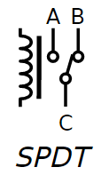
In the preceding diagram, we're looking at the schematic representation of the non-energized state of the circuit. As you can see, the B-C circuit corresponds to the normally closed (NC) state, while the A-C circuit represents the normally open (NO) state.
Now that we have the key component in place, let's integrate it into a simple circuit to demonstrate its functionality. We'll design the circuit so that when voltage is applied to the IPP, the switch will toggle, and an LED will illuminate on the output side.
I'll start by illustrating the simple circuit.
The Relay: A Bridge Between Three Circuits
Our relay module consists of three separate circuits, each with its own distinct function.
- First, there's the input circuit, which plays a crucial role in determining which output circuit is active.
- Then, there's the normally closed (NC) output circuit, which remains active when no voltage is applied to the IPP. As you can see in the next diagram, when the IPP is not powered, the LED on the NC output circuit is illuminated.
- Lastly, there's the normally open (NO) output circuit, which is designed to operate in tandem with the NC circuit.
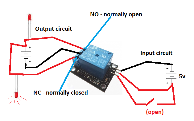
If we were to activate the switch in the input circuit, the state of the output circuit would change. The switch would toggle, causing the normally closed (NC) circuit to open, which would extinguish the LED. Simultaneously, the normally open (NO) circuit would close, allowing the top LED in the diagram to illuminate.
Have We Devoted Too Much Attention To The Relay Module?
Perhaps, but consider the significance of this fundamental component. Mastering its operation unlocks a vast range of control possibilities, empowering you to tackle a multitude of future projects.
Moreover, this relay is the linchpin of our current project, as it provides the electronic switch we need to flip. By grasping this concept, you'll be able to harness the power to control a wide spectrum of electrical devices, limited only by your imagination.
What Triggers The Relay's Voltage Application Remains A Question.
I manually applied the 5V to the input pin using a wire.
Signal Activation
We need to find a way to send a signal to the relay, instructing it to activate and flip the switch, thereby starting the garage door motor (GDM).
One possible approach would be to create a wired solution, where pressing a button from a distance would apply 5V to the wire connected to the relay module's IPP, activating the magnetic coil and starting the GDM. However, this is not a practical solution for our situation, as it's essentially what we already have with our wall switch. Instead, we want to receive a wireless signal to activate the GDM.
Bluetooth, being a wireless technology, offers a promising solution. I've been following Adafruit Industries' videos and keeping up with their innovative DIY electronics and kits, and I believe I've seen some affordable Bluetooth components that could fit the bill.
The Bluetooth
In an effort to keep costs and complexity to a minimum, I began searching for a suitable Bluetooth module. My search led me to a remarkably simple, albeit poorly documented, module that appears to be an industry de facto standard, with multiple manufacturers producing their own versions.
HC-05 Bluetooth Module
I finally settled on a particular Bluetooth module, which I was able to purchase from Amazon for approximately $8.00USD. The specific model I chose is the HC-05 Wireless Bluetooth Serial Transceiver Module, available in both slave and master configurations. Below, you can see the front and back views of the module.
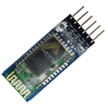
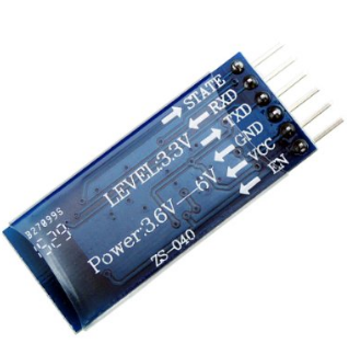
Device Pins: Gateways to Functionality
The back view of the module provides valuable insights into its operation. We can see that powering up the device requires a simple connection: providing 3.6v to 6v to the VCC pin and grounding the GND pin to complete the circuit.
Using the Bluetooth Module (Mostly) Straightforward
In essence, if we were to connect the module to a breadboard, add a power source within the 3.6v-6v range, and wire it up correctly, the module would begin broadcasting a Bluetooth signal, allowing other devices to connect.
The Key Question: Communicating with the Bluetooth Device
However, once the module is powered up, broadcasting, and a device has connected, the crucial question remains: how do we communicate with the Bluetooth device? How do we receive messages from the connected device and use them to activate our relay, ultimately starting the garage door motor (GDM)? We'll explore the answer to this question soon. For now, let's continue examining the Bluetooth module's pins and their functions. Before we do, though, it's essential to discuss the importance of voltage compatibility when selecting components.
Voltage Considerations
It's crucial to note the voltage ranges of our devices. The relay module operates within a range of 5v to 12v, while the Bluetooth module functions within a narrower range of 3.6v to 5v. This is significant, as we'll need to ensure that our power supply can accommodate both devices on the same circuit. Later, when we discuss the Atmel ATMega328 chip, we'll learn that it has an operating voltage range of 1.8v to 5.5v.
Now, let's refocus on the HC-05 Bluetooth module. It's time to connect it, pair it with a device, and explore its capabilities.
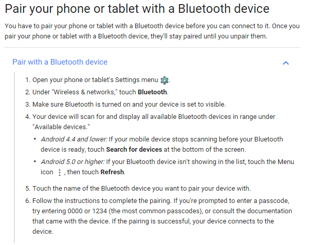
Bring Up Bluetooth Module And Start Pairing
The general steps on how to pair a device is shown as follows. The default password for the HC-05 module is 1234 and we will need to generate a dynamic one in the next tutorial.
Interacting with the Bluetooth Module
Now that we've successfully paired a device with the Bluetooth module, we need to understand how to communicate with it. How can we send and receive data from the module, and how can we confirm that we're successfully interacting with it?
The Bluetooth Module's Simple Functionality
The Bluetooth module's primary function is straightforward: it sends and receives data. The challenging part is working with the received data. Essentially, the module performs two key tasks:
It receives wireless data and transmits it to its serial transmit pin (Tx) as a series of voltages, similar to Morse code. When data is written to the Rx pin on the Bluetooth module, it converts that data into a wireless signal and transmits it. This means that if we can detect when voltages are present on the Tx pin, we can determine that a message is available to read. Conversely, if we want to send a message via the Bluetooth module, we need to write voltages to the Rx pin.
The Data Dilemma
The crux of the issue is that we can't access the data received by the Bluetooth module. Take a moment to consider this problem. How can we read the voltages on the Tx pin? One possible approach would be to directly connect the Tx pin to the relay's IPP (input port). However, this would result in every bit of data received by the Bluetooth module triggering the relay numerous times a second, causing the garage door motor (GDM) to activate and deactivate rapidly. This solution is clearly impractical.
The Need for Processing Power
What we really need is a component that can process the incoming data from the Bluetooth module. We require a way to write a program that can analyze the data and make decisions based on it. Since the Bluetooth module itself cannot be programmed to process data, we need another component to perform this task. This is where the ATMega328PU microprocessor comes in – the central processor of our project.
The Atmel ATMega Chips
As a product developer, I'm more concerned with getting our project done efficiently and cost-effectively. Let's focus on the ATMega chip from a practical perspective. What's driving the popularity of these chips?
The AVR chips, first introduced in 1996, were among the pioneers in the microcontroller market. They...
"..one of the first microcontroller families to use on-chip flash memory for program storage, as opposed to to one-time programmable ROM, EPROM, or EEPROM used by other microcontrollers at the time."
This innovative technology enabled the AVR chips to have programs easily flashed into their memory, a significant advantage over their predecessors.
Arduino Boards
The pioneering work of Massimo Banzi and his team paved the way for the creation of Arduino, an open-source hardware platform that revolutionized the world of embedded programming.
In 2005, the first Arduino boards were released, offering an affordable ($30-$40) and accessible way for hobbyists to dive into embedded programming. The team chose to base Arduino on Atmel chips due to their:
- Low cost
- Easy programming (flash memory)
- Simple programming (easy to write programs for)
- Built-in functionality (serial communication, etc.)
- Good performance
Prior to Arduino, hobbyists faced a significant barrier to entry, with investments of hundreds of dollars just to get started with programming a chip. Arduino and Atmel chips dramatically reduced this cost, making embedded programming more accessible to a wider audience.
The open-source nature of Arduino development boards further drove down prices, as anyone could build and sell them. This democratization of embedded programming enabled a new generation of makers and innovators to explore the world of microcontrollers.
The ATMega328: A Cost-Effective Solution
One of the key advantages of the ATMega328 is its affordability. I was able to purchase two of these chips for a mere $10.99USD on Amazon, complete with the Arduino UNO bootloader: Amazon.com.
Seamless Serial Communication
The ATMega328 also offers easy access to its functionality via its pins, including built-in serial communication capabilities. This is particularly useful for our project, as we can leverage the chip's Transmit (Tx) and Receive (Rx) pins for serial communication. For a detailed look at the chip's pins, refer to the diagram from Atmel's documentation.
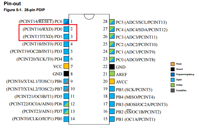
As indicated by the red box, the diagram above shows two serial communication pins labeled TXD and RXD.
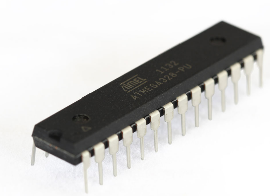
The 28-pin ATMega328P chip is depicted as follows:
Connecting Bluetooth is a breeze
As you'll soon see, these pins make it incredibly convenient to connect our chip to the Bluetooth module, enabling us to receive data from Bluetooth and transmit data back via Bluetooth. The process involves simply linking the Bluetooth's Tx to the chip's RXD and the Bluetooth's Rx to the chip's TXD.
Next, let's establish power connections for the ATMega chip and the Bluetooth module, and then create a C program to be flashed onto the chip, which will retrieve data from the Bluetooth device.
Configuring the Flash Programmer
To begin, we need to set up our board to enable flashing of our program to the chip - essentially, writing our program into the ATMega chip's flash memory.
Typically, we would be using an Arduino programming board at this stage. However, I prefer a more cost-effective approach, opting to work directly with the chip's core and program in pure C. Therefore, I'm recommending an alternative device.
I highly recommend purchasing the following flash programmer, which has proven to be very effective and affordable ($10.50USD):
Configuring the Flash Programmer
Obtain the Necessary Drivers
Begin by connecting the device to your USB port and installing the required drivers from:
Installing AVRDude
Next, download and install AVRDude, a free and open-source software that compiles your C programs using the GNU C compiler and flashes the program into your chip's memory.
You can obtain AVRDude from: /releases/avrdude
Download the latest release, extract the files, and then you'll be able to run AVRDude from the command line.
Overcoming Setup Obstacles
While I'm aware that setting up this programming environment can be challenging, I'll keep this article concise and won't delve into the details.
Valuable Resource for Setup
The book that helped me navigate the process and start programming Atmel chips is: AVR Programming: Learning to Write Software for Hardware by Elliot Williams, eBook - Amazon.com. You don't need to read the entire book, but the first two chapters will provide sufficient guidance to get you set up.
From this point on, I'll assume that you have your environment configured, connected, and are ready to flash a program to the chip.
Bluetooth Module Byte Reading Program Example in C
Here is a straightforward C program that reads incoming bytes from the Bluetooth module and subsequently determines the course of action based on the received data.
#include <avr/io.h>
#include <util/delay.h>
#include "pinDefines.h"
#include "USART.h"

int main(void) {
  char serialCharacter;
  DDRB |= 0b0000001;
  initUSART();

  while (1) {
    serialCharacter = receiveByte();
    transmitByte(serialCharacter);
    if (serialCharacter == 'y')
    {
        PORTB = 0b00000001;
    }
    if (serialCharacter == 'n')
    {
        PORTB = 0b00000000;
    }
    _delay_ms(100);
  }
  return 0;
}
This is just a simple example. In the next tutorial, I will explain how to develop the software stack step by step.
This tutorial shows the softeware part of EaseLock. I assume you have finished seting up the hardware part of EaseLock during my last tutorial in Hardware Tutorial, as to ensure we are in the same context even though the design article has been devided.
Conduct A Meticulous Analysis of The Code
Let's conduct a meticulous analysis of the code, breaking it down into individual steps to elucidate the functionality of this straightforward program. The code in question is a modified version of Elliot Williams' (author of the aforementioned AVR Programming book) work, which can be accessed on his GitHub repository: hexagon5un/AVR-Programming, specifically in the serialLoopback.c file.
Obtain the Complete Project in a Single Zip File
You can download the entire sample project, neatly packaged in a single zip file (ActivateDoor.zip) located at the download page. This zip file also includes a makefile for the project, which allows you to build the project by simply typing "c:>make" in the command line, provided your GNU C toolchain is set up correctly (which is the case if you've installed WinAVR). This will generate the activateDoor.hex file, which is the file that gets uploaded to the ATMega328P chip.
Header Files
The first four lines of code reference the libraries used by this program. The ones enclosed in brackets are part of the AVR-C standard library or the C standard libraries, and are included in your WinAVR installation and the GNU C toolchain.
The other two files, pinDefines.h and USART.h, are additional libraries for this program, obtained from Elliot Williams' GitHub repository. These libraries provide functionality for reading and writing to the serial pins (Tx and Rx) on the ATMega328P.
Using the makefile (also provided by Elliot Williams) simplifies the process, as typing "c:\ActivateDoor>make flash" will instruct the GCC compiler to follow the make script, build the executable (.hex file), and flash it into the chip's memory in one step.
The first task the code performs inside the main() function is to set up a variable to hold a character that will be read from the RXD pin, which is the value sent to us via Bluetooth.
Configure Output Pin
The line "DDRB |= 0b0000001;" prepares the PORT B pins for output by setting the first bit of PORT B to a voltage, indicating to the chip that the pin is available for writing to. This line uses a bit operator to set the first bit of PORT B, which corresponds to PB0 (pin number 14 in the diagram).
Initialize Serial Pins
We also need to prepare the serial pins for sending and receiving, which is conveniently handled by the code in the usart.h library and the implementation of initUSART() in the usart.c file, included in the project zip. We don't need to delve into the details, as this work is already done for us.
Before we dive into the infinite while loop, let's take a moment to appreciate the fact that the chip we're using is a fully functional computer.
AVR Chip: A Self-Contained Computer
When you connect the ATMega328P chip's VCC pin (pin 7 in the diagram) to 5V and the ground pin (pin 8) to ground, the chip will automatically start executing the program stored in its memory. This is true even if no other components are connected to the chip. However, if there is no program stored in the chip's memory, or if there are no output devices connected to the chip, you won't be able to observe its operation.
As Long as Power is Available, the Program Runs
The key point here is that as long as the chip has power, it will continue to execute the program. This is why we use an infinite loop construct, such as the following:
while (1) { // perform some action... }
This creates a program loop that will continue to run as long as the chip has power.
The first line within our loop is:
serialCharacter = receiveByte();
This line calls a pre-written USART function to retrieve any incoming byte (character) and store it in our char variable.
The next line is somewhat unusual:
transmitByte(serialCharacter);
We then transmit the received character back out using another library function. I did this to verify that I could see the characters I typed echoed back to me on the terminal screen during program testing.
The Core Functionality
Finally, we arrive at the interesting code that performs the actual functionality. This is the core of our entire system and enables communication with the Android program. (Later, we'll explore how the Android program sends character values to our Bluetooth module.)
When a character is received, we check its value. If it's the letter Y, we apply voltage to PB0 (Pin 14), and if it's an N, we remove voltage from PB0.
if (serialCharacter == 'y')
 {
     PORTB = 0b00000001;  // set voltage high (5v) on PB0
 }
 if (serialCharacter == 'n')
 {
     PORTB = 0b00000000;  // set voltage low (less than 5v (0v)) on PB0
 }
PB0 (Pin 14) Directly Controls the Relay Input Port
Now that we've examined the code, the entire system's operation becomes clear. Since PB0 is directly connected by wire to the input port on our relay, it controls when the relay switches on and off.
As a result, when the relay switches, the output circuit is activated, and the switch on the ODM (overhead door motor) is closed, ultimately activating the motor.
The Missing Piece: The Android App
Now, the only remaining component is the Android app, which enables us to pair with our Bluetooth module and send values to set PB0 high and low, thereby activating and deactivating the switch.
To develop the Bluetooth Android app, I relied heavily on the official Google documentation at: Bluetooth | Android Developers.
You can download the Android app at the download page and build it using Android Studio.
Note that the app only requests permissions to control and set up Bluetooth, so it's not overly intrusive.
Android App: The Initial Unrefined Version
Instead of polishing the app's UI for this tutorial, I've decided to share the rough version with you, providing a closer look at the development process.
The app's interface appears as follows:
The app loads a list of paired Bluetooth devices at the top.
To connect to your Bluetooth module after powering it up, simply tap the device in the top list.
When you select the device, the app sends test data to the Bluetooth device and displays a message to indicate whether the connection was successful.
The app prints a status message in the bottom scrollable list, regardless of whether the connection succeeds or fails.
Semi-Manual Operation
If the initial connection is successful, click the [Yes] button to send the "y" character, which activates the relay. However, you'll need to manually deactivate the relay, so after clicking the [Yes] button, click the [No] button.
Each time you click a button, a new status message is written to the bottom scrollable list, confirming that the app has taken the desired action.
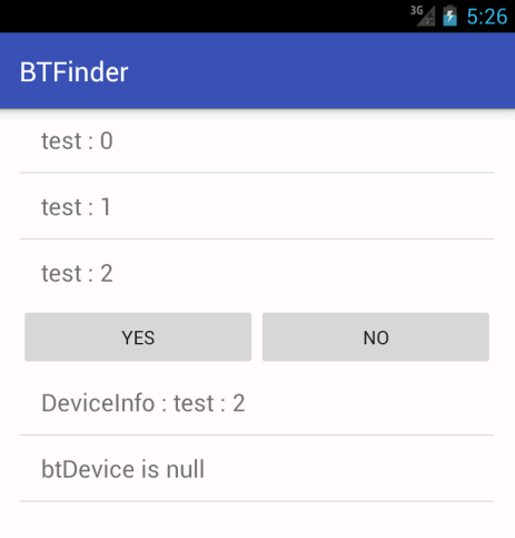
Android Development Challenge: No Bluetooth Emulation
One of the significant challenges of developing the Bluetooth app is the lack of Bluetooth emulation on Android emulated devices. This means that the only way to test the app is to deploy it to a physical device, run the app, and observe the results. This is why I included numerous status messages written to the scrollable list view.
When you launch the app, it will appear as follows: (Note that this screenshot was taken on an emulator, but imagine each test item representing a Bluetooth device)
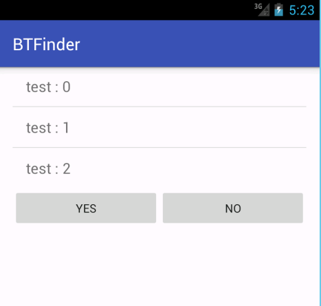
One of those items will likely be named HC-05 (our Bluetooth module).
Next, you would simply tap the item in the top list, and the app will attempt to connect to the device and send test data.
On the emulator, it will fail, but at least it provides some output, giving you an idea of what's happening.
If you run the app on a real device and it connects successfully, it will appear as follows:
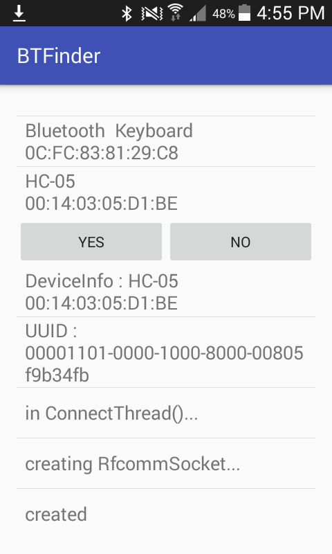
Finally, after establishing a successful connection, clicking the [Yes] button will set the PB0 pin high (to 5V) and activate the relay.
To keep things concise, here is the code in the ConnectThread.java class that writes the "y" and "n" characters:
public void writeYes() {
    try {
        byte [] outByte = new byte[]{121};

        mmOutStream.write(outByte);
        logViewAdapter.add("Success; Wrote YES!");
        logViewAdapter.notifyDataSetChanged();

    } catch (IOException e) { }
}

public void writeNo() {
    try {
        byte [] outByte = new byte[]{110};
        mmOutStream.write(outByte);
        logViewAdapter.add("Success; Wrote NO");
        logViewAdapter.notifyDataSetChanged();

        mmOutStream.write(outByte);
    } catch (IOException e) { }
}
As you can see, in the writeYes() method, we set outByte to the ASCII value 121, which represents the lowercase letter "y". Similarly, in the writeNo() method, we set outByte to 110, which corresponds to the lowercase letter "n". It's a straightforward process.
Additionally, the app writes a brief message to inform you that it has written bytes to the stream, which is then transmitted over the Bluetooth signal.
Stop Others From Opening My Door
Currently, the system operates in an ideal environment, but the lack of authentication mechanisms makes it vulnerable to attacks. Unauthorized individuals can easily open the door without permission, compromising security and privacy.
To prevent unauthorized access to my door, it is essential to implement a robust authentication process that verifies the legitimacy of the user before allowing interaction with the door. The proposed solution involves adding a password authentication step before sending and executing door commands.
Dynamic Password Generation and Modification
To bring an additional layer of security to the system, the password can be generated dynamically or modified by legitimate users. This ensures that the password is not static and reduces the risk of unauthorized access.
Authentication Procedure
The authentication procedure involves the following steps:
- Android App Connected to ATMega328P via Bluetooth: The Android app establishes a Bluetooth connection with the ATMega328P microcontroller.
- Android App Sends Authentication Message to Prove Itself: The Android app sends an authentication message to the ATMega328P to prove its legitimacy.
- ATMega328P Verifies the Authentication Message and Authorizes the Connection: The ATMega328P verifies the authentication message and authorizes the connection if the message is valid.
- Android App Sends Door Command Message or Requests to Change Password: Once the connection is authorized, the Android app can send door command messages or request to change the password.
- Connection Closed: After the door command is executed or the password is changed, the connection is closed.
Challenges in Implementing the Authentication Procedure
Although the procedure seems straightforward, there are several challenges to overcome:
- Data Transmission Limitations: The size of the data transmission in one round can vary from 1 byte to multiple bytes (streams), and its size is not fixed.
- Message Type Identification and Categorization: There are multiple message types involved, including authentication messages, change password messages, and door command messages, which need to be identified and categorized.
Communication Convention
To achieve the authentication procedure in code, a communication convention needs to be negotiated for both sides. The proposed convention involves using:
- 1 byte to identify the message type: The first byte of the message is used to identify the message type (e.g., authentication, change password, door command).
- 2 bytes to identify the message size: The next two bytes are used to specify the size of the message payload.
- Payload in message size: The remaining bytes are used to carry the payload of the message. Code for Communication Convention
Here is an example code snippet in android app demonstrates the communication convention:
public class Message {
    public byte msgType;
    public short msgSize;
    public byte[] payload;

    public Message(byte msgType, short msgSize, byte[] payload) {
        this.msgType = msgType;
        this.msgSize = msgSize;
        this.payload = payload;
    }

    public static final byte MSG_TYPE_AUTH = 0x01;
    public static final byte MSG_TYPE_CHANGE_PASSWORD = 0x02;
    public static final byte MSG_TYPE_DOOR_COMMAND = 0x03;

    public byte[] pack() {
        // Convert the message to a byte array
        byte[] messageBytes = new byte[3 + msgSize];
        messageBytes[0] = msgType;
        messageBytes[1] = (byte) (msgSize >> 8);
        messageBytes[2] = (byte) (msgSize & 0xFF);
        System.arraycopy(payload, 0, messageBytes, 3, payload.length);
        return messageBytes;
    }

    public static Message createAuthMessage(byte[] payload) {
        return new Message(MSG_TYPE_AUTH, (short) payload.length, payload);
    }

    public static Message createChangePasswordMessage(byte[] payload) {
        return new Message(MSG_TYPE_CHANGE_PASSWORD, (short) payload.length, payload);
    }

    public static Message createDoorCommandMessage(byte[] payload) {
        return new Message(MSG_TYPE_DOOR_COMMAND, (short) payload.length, payload);
    }
}
Find Storage To Store Crendentials
The ATMega328P microcontroller has a limited amount of storage capacity, which includes:
- Flash Memory: 32 KB of flash memory for storing the program code.
- SRAM (Static Random Access Memory): 2 KB of SRAM for storing data temporarily while the program is running.
- EEPROM (Electrically Erasable Programmable Read-Only Memory): 1 KB of EEPROM for storing data that needs to be retained even when the power is turned off.
Considering the storage limitations of the ATMega328P, we can store the passwords in the EEPROM, which provides a non-volatile storage solution. This means that the passwords will be retained even when the power is turned off. However, the EEPROM has a limited number of write cycles (approximately 100,000), which may not be suitable for frequent password changes.
We'll use the EEPROM library, which is part of the Arduino framework, to interact with the EEPROM.
Password Storage Structure
To store the password, we'll use a simple structure:
typedef struct {
  char password[16]; // 16 characters max
  uint8_t passwordLength; // length of the password
} password_t;
Storing the Password
To store the password, we'll use the EEPROM.write() function:
void storePassword(char* password) {
  password_t pwd;
  strncpy(pwd.password, password, 16);
  pwd.passwordLength = strlen(password);

  EEPROM.write(0, pwd); // store at address 0
}
Retrieving the Password
To retrieve the password, we'll use the EEPROM.read() function:
char* retrievePassword() {
  password_t pwd;
  EEPROM.read(0, pwd); // read from address 0

  char* password = (char*)malloc(pwd.passwordLength + 1);
  strncpy(password, pwd.password, pwd.passwordLength);
  password[pwd.passwordLength] = '\0'; // null-terminate

  return password;
}
Preventing Replay Attack
A replay attack occurs when an attacker intercepts and records a valid authentication message, and then replays it to gain unauthorized access to the system. To prevent replay attacks, we need to ensure that each authentication message is unique and cannot be reused.
Why preventing replay attack is necessary? Replay attacks can be devastating to our door control system. If an attacker can replay a valid authentication message, they can gain unauthorized access to the system and open the door without permission. This can compromise the security and privacy of the system.
Challenge-Response Method
One way to prevent replay attacks is to use a challenge-response method. In this method, the ATMega328P microcontroller generates a random challenge and sends it to the Android app. The Android app then responds with a response message that includes the challenge and a hash of the password. The ATMega328P microcontroller verifies the response message by checking the challenge and the hash of the password.
To implement the challenge-response method, we need to add a new message type to the communication convention. Let's call it MSG_TYPE_CHALLENGE_RESPONSE.
Firstly, the Android App sends a MSG_TYPE_AUTH message to the device and nn the board side, we can generate a random challenge and send it to the Android app. Further, the Android App sends a MSG_TYPE_CHALLENGE_RESPONSE message to the device to verify.
On the board side, we can generate a random challenge using current timestamp together with a secret string, send it to the Android app.
byte storedChallenge[16];// 16-byte challenge

void sendChallenge() {
    unsigned long timestamp = millis(); // get the current timestamp
    storedChallenge[0] = (byte) (timestamp >> 24);
    storedChallenge[1] = (byte) (timestamp >> 16);
    storedChallenge[2] = (byte) (timestamp >> 8);
    storedChallenge[3] = (byte) timestamp;

    // Fill the remaining bytes with a secret string "ethan'slock"
    const char* fixedString = "ethan'slock";
    memcpy(&storedChallenge[4], fixedString, 12);

    Message challengeMessage;
    challengeMessage.type = MSG_TYPE_CHALLENGE_RESPONSE;
    challengeMessage.length = 16;
    memcpy(challengeMessage.payload, storedChallenge, 16);
    sendMessage(&challengeMessage);
}
When working in the constrained environment of the board where external libraries are not permitted, a straightforward approach to implement the challenge response verfication function is to to hash a password and a challenge using a basic XOR operation. Although this method does not provide the cryptographic security of standard algorithms like SHA-256, it serves well in scenarios where simplicity is paramount.
The function combines the challenge and password by performing a byte-wise XOR operation. This approach ensures that the resultant hash is a unique representation of both inputs.
#define CHALLENGE_SIZE 16
#define PASSWORD_SIZE 16
#define RESPONSE_SIZE 16

// Function to hash password with challenge using XOR operation
void hashPassword(const unsigned char *challenge, const unsigned char *password, unsigned char *hashed) {
    for (int i = 0; i < CHALLENGE_SIZE; i++) {
        hashed[i] = challenge[i] ^ password[i];
    }
}

// Function to verify the challenge-response
int verifyChallengeResponseMessage(Message message) {
    if (message.length < 32) {
        // Payload is too short to be valid
        return 0;
    }

    byte challenge[CHALLENGE_SIZE]; // 16-byte challenge
    byte clientResponse[RESPONSE_SIZE]; // 16-byte password hash
    unsigned char expectedResponse[RESPONSE_SIZE];

    // Extract the challenge and response from the message payload
    memcpy(challenge, message.payload, CHALLENGE_SIZE);
    memcpy(clientResponse, message.payload + CHALLENGE_SIZE, RESPONSE_SIZE);

    // Hash the stored challenge and password
    hashPassword(storedChallenge, storedPassword, expectedResponse);

    // Verify the challenge and response
    if (memcmp(challenge, storedChallenge, CHALLENGE_SIZE) == 0 &&
        memcmp(clientResponse, expectedResponse, CHALLENGE_SIZE) == 0) {
        // Authentication successful
        return 1;
    } else {
        // Authentication failed
        return 0;
    }
}
On the app side, we can receive the challenge information and generate a response message based on the challenge.
public static final byte MSG_TYPE_CHALLENGE_RESPONSE = 0x04;
public static Message createChallengeResponseMessage(byte[] challenge, byte[] passwordHash) {
    byte[] payload = new byte[challenge.length + passwordHash.length];
    System.arraycopy(challenge, 0, payload, 0, challenge.length);
    System.arraycopy(passwordHash, 0, payload, challenge.length, passwordHash.length);
    return new Message(MSG_TYPE_CHALLENGE_RESPONSE, (short) payload.length, payload);
}
Figuring Out The Timestamp Problem
When developing an Android app to control a door lock via Bluetooth, one crucial aspect to consider is timestamp management. To ensure secure communication, our system requires a reliable timestamp mechanism to prevent replay attacks. Since the ATMega328P microcontroller does not have a built-in Real-Time Clock (RTC) module, we need to implement a software-based solution to generate and manage timestamps.
It's essential to note that we don't require an exact timestamp; instead, we need an incremental timestamp that increments monotonically. This ensures that even if the device reboots, it can synchronize its timestamp before accepting new authentication messages, thereby preventing replay attacks.
Synchronize Timestamp From Android App On Request
To maintain timestamp consistency between the Android app and the board, we need to synchronize the timestamp at regular intervals. This can be achieved by sending a timestamp synchronization message from the Android app to the board. We can introduce a new message type, MSG_TYPE_SYNC_TIMESTAMP, to the communication protocol to facilitate this process.
Here's an updated code snippet in the Android app:
public static final byte MSG_TYPE_SYNC_TIMESTAMP = 0x05;

public static Message createSyncTimestampMessage(long timestamp) {
    byte[] payload = new byte[4];
    payload[0] = (byte) (timestamp >> 24);
    payload[1] = (byte) (timestamp >> 16);
    payload[2] = (byte) (timestamp >> 8);
    payload[3] = (byte) timestamp;
    return new Message(MSG_TYPE_SYNC_TIMESTAMP, (short) payload.length, payload);
}
This code defines a new message type, MSG_TYPE_SYNC_TIMESTAMP, and a method to create a timestamp synchronization message. The method takes a long timestamp value as input, converts it into a byte array, and returns a Message object with the appropriate message type and payload.
Fixing The Data Trunk Truncated Or Missing Problem
Problem Statement
During the development I encountered an issue where the authentication process would fail, even when the correct password was entered. Upon further investigation, I discovered that the problem was caused by truncated or missing data in the transmission process.
After conducting a thorough debugging process, I found that the data truncation issue occurred deterministically when the data buffer was large. On the other hand, the data missing problem occurred randomly. I suspected that the Bluetooth transmission mechanism was unreliable, leading to the data missing issue. Furthermore, I discovered that when transmitting a buffer size larger than the Maximum Transmission Unit (MTU) size, the remaining data would be truncated.
Understanding the Bluetooth Transmission Mechanism
To better understand the root cause of the problem, I delved into the technical details of Bluetooth transmission. Bluetooth is a wireless personal area network technology that operates on the 2.4 GHz frequency band and it uses a master-slave architecture, where one device acts as the master and the other as the slave. In our case, the Android app acts as the master, and the door control system acts as the slave.
Bluetooth transmission is based on a packet-based protocol, where data is divided into packets and transmitted over the air. Each packet has a maximum size limit, known as the MTU size, which varies depending on the Bluetooth device and the operating system. When transmitting a large amount of data, it is divided into multiple packets, and each packet is transmitted separately.
Causes of Data Truncation and Missing
There are two primary causes of data truncation and missing in Bluetooth transmission:
- MTU Size Limitation: When transmitting a buffer size larger than the MTU size, the remaining data is truncated, leading to data loss.
- Unreliable Transmission: Bluetooth transmission is not reliable, and packets can be lost or corrupted during transmission, resulting in missing data.
To overcome the data truncation and missing problem, I implemented the following solutions:
- Packet Fragmentation: I implemented packet fragmentation to divide large data buffers into smaller packets, each within the MTU size limit. This ensures that no data is truncated due to MTU size limitations.
- Error Detection and Correction: I implemented error detection and correction mechanisms to detect and retransmit corrupted or lost packets. This ensures that all data is transmitted reliably and accurately.
Adjust the MTU size
The MTU size is typically fixed and depends on the Bluetooth device and operating system. To set the MTU size of the HC-05 Bluetooth module using C programming, you just need to send a specific AT command to the module, that is AT+MTU=32\r\n, and remember to modify the Android app code accordingly:
public void run() {
        byte[] buffer = new byte[32];  // buffer within MTU size, the size MUST not exceed the MTU size of the HC-05 Bluetooth module
        int bytes; // bytes returned from read()
        logViewAdapter.add("Reading from BT!...");
        logViewAdapter.notifyDataSetChanged();
        // Keep listening to the InputStream until an exception occurs
        while (true) {
            try {
                // Read from the InputStream
                bytes = mmInStream.read(buffer);
                // Send the obtained bytes to the UI activity
                logViewAdapter.add(String.valueOf(bytes));
                logViewAdapter.notifyDataSetChanged();
            } catch (IOException e) {
                logViewAdapter.add("IOException on read: " + e.getMessage());
                logViewAdapter.notifyDataSetChanged();
            }
        }
    }
You may wonder why we need to set a small MTU size. Well, it's for compatibility reasons, as a larger MTU size results in less compatibility.
Extending Packet Header Format
To implement packet fragmentation and reassembly, we need to design a packet header format that includes the necessary fields to identify and reassemble the packets. Here is an extended packet header format:
| Field | Length(bytes) | Description | Is New Extended |
|---|---|---|---|
| Packet Number (PN) | 2 | Unique packet number for reassembly. Each message should have a different PN | new |
| Sequence Number (SN) | 1 | Sequence number for packet ordering. The most significant bit(MSB) is set to 1 for first packet,otherwise MSB is 0. The 7 least significant bits (LSB) are used to store the packet sequence number in decreasing order | new |
| Checksum (CK) | 2 | checksum for error detection. CRC-16 is used for payload checksum. The checksum of the first packet is calculated upon total packets, the subsequent packet checksum is calculated on packet payload | new |
| Message Type (MT) | 1 | Identify the message type | |
| Message Size (MS) | 2 | Length of the packet fragment payload (or total length for first packet to help checksum verfication) | |
| Payload | variable | Packet payload data |
public class Message {
    public byte msgType;
    public short msgSize;
    public byte[] payload;

    public Message(byte msgType, short msgSize, byte[] payload) {
        this.msgType = msgType;
        this.msgSize = msgSize;
        this.payload = payload;
    }

    public static final byte MSG_TYPE_AUTH = 0x01;
    public static final byte MSG_TYPE_CHANGE_PASSWORD = 0x02;
    public static final byte MSG_TYPE_DOOR_COMMAND = 0x03;
    public static final byte MSG_TYPE_CHALLENGE_RESPONSE = 0x04;
    public static final byte MSG_TYPE_SYNC_TIMESTAMP = 0x05;

    public static Message createAuthMessage(byte[] payload) {
        return new Message(MSG_TYPE_AUTH, (short) payload.length, payload);
    }

    public static Message createChangePasswordMessage(byte[] payload) {
        return new Message(MSG_TYPE_CHANGE_PASSWORD, (short) payload.length, payload);
    }

    public static Message createDoorCommandMessage(byte[] payload) {
        return new Message(MSG_TYPE_DOOR_COMMAND, (short) payload.length, payload);
    }

    public static Message createChallengeResponseMessage(byte[] challenge, byte[] passwordHash) {
        byte[] payload = new byte[challenge.length + passwordHash.length];
        System.arraycopy(challenge, 0, payload, 0, challenge.length);
        System.arraycopy(passwordHash, 0, payload, challenge.length, passwordHash.length);
        return new Message(MSG_TYPE_CHALLENGE_RESPONSE, (short) payload.length, payload);
    }

    public static Message createSyncTimestampMessage(long timestamp) {
        byte[] payload = new byte[4];
        payload[0] = (byte) (timestamp >> 24);
        payload[1] = (byte) (timestamp >> 16);
        payload[2] = (byte) (timestamp >> 8);
        payload[3] = (byte) timestamp;
        return new Message(MSG_TYPE_SYNC_TIMESTAMP, (short) payload.length, payload);
    }
}
Packet Fragmentation
When sending a large data buffer, we divide it into smaller packets using the following algorithm:
- Calculate the maximum packet size (MPS) based on the MTU size (32 bytes).
- Divide the data buffer into packets of size MPS.
- Assign a unique Packet Number (PN) to each packet in incremental order.
- For the first packet, set the MSB of Sequence Number (SN) to 1 and the rest of 7 LSB to MPS, set the Packet Length (PL) to the total length of all packets.
- For subsequent packets, set the MSB of Sequence Number (SN) to 0 and the rest of 7 LSB to a decreasing value starting from MPS minus 1 (e.g., 0x1F, 0x1E, ..., 0x1) and the Packet Length (PL) to the length of the packet payload.
- For the first packet, calculate the Checksum (CK) for all packets using a checksum algorithm CRC-16.
- For subsequent packets, calculate the Checksum (CK) for each packet using a checksum algorithm CRC-16.
- Construct the packet header using the PN, SN, MT,MS and CK fields.
- Transmit each packet over Bluetooth.
Here's an updated code snippet of class Message in the Android app to support packet fragmentation:
    public static short globalPktNO = 0;

    public static synchronized short generatePacketNumber() {
        return ++globalPktNO;
    }

    public static byte[][] fragmentPacket(Message msg, int mtuSize){
        if (mtuSize <= 8) {
            return null;
        }

        short pktID = Message.generatePacketNumber();
        int numPackets = (int) Math.ceil((double) msg.payload.length / (mtuSize - 8));
        byte[][] packets = new byte[numPackets][];

        for (int i = 0; i < numPackets; i++) {
            int packetSize = Math.min(mtuSize - 8, msg.payload.length - i * (mtuSize - 8));
            byte[] packet = new byte[mtuSize];

            // set Packet Number
            packet[0] = (byte) (pktID >> 8); // pktNO
            packet[1] = (byte) (pktID & 0xFF); // pktNO

            // set Sequence Number
            packet[2] = (byte) ((i == 0) ? 0x80 : 0x00); // seqNO MSB
            packet[2] = (byte) (packet[2] | (numPackets - i)); // seqNO

            // set Message Type
            packet[5] = (byte) msg.msgType; // msgType

            // set Message Size
            short msize = (short)((i == 0) ? msg.payload.length : packetSize);
            packet[6] = (byte) ((msize >> 8) & 0xFF); // message size high byte
            packet[7] = (byte) (msize & 0xFF); // message size low byte

            // set current packet payload
            byte[] pdata = new byte[packetSize];
            System.arraycopy(msg.payload, i * (mtuSize - 8), packet, 8, packetSize);
            System.arraycopy(packet, 8, pdata, 0, packetSize);
            // set Checksum
            short chksum = crc16((i == 0)? msg.payload : pdata);
            packet[3] = (byte) (chksum >> 8); // checksum high byte
            packet[4] = (byte) (chksum & 0xFF); // checksum low byte
            packets[i] = packet;

        }
        return packets;
    }
Packet Reassembly
At the receiving end, we reassemble the packets using the following algorithm:
- Receive each packet and extract the PN, SN, MS, MT, and CK fields from the packet header.
- Verify the Checksum (CK) to ensure the packet is not corrupted.
- Use the MSB of Sequence Number (SN) field to determine whether the packet is the first packet or a subsequent packet.
- Use the rest of 7 LSB in Sequence Number (SN) to determine the total number of packets and the correct order of the packets.
- Reassemble the packets in the correct order using the Packet Number (PN) and Sequence Number (SN) fields.
- Verify the reassembled packet using the Checksum (CK) field.
Here's an updated code snippet of class Message in the Android app to support packet reassembly:
    public static Message assemblePacket(byte[][] packets, int mtuSize) throws IOException{
        if (packets == null || packets.length == 0) {
            return null;
        }

        // Extract the packet number, sequence number, total message size and message type from the first packet
        short pktNO = (short) (((packets[0][0] & 0xFF) << 8) | (packets[0][1] & 0xFF));
        byte seqNO = packets[0][2];
        byte msgType = packets[0][5];
        short totalSize = (short) (((packets[0][6] & 0xFF) << 8) | (packets[0][7] & 0xFF));

        // Create a new byte array to store the reassembled payload
        byte[] payload = new byte[totalSize];

        // Reassemble the payload
        int offset = 0;
        for (byte[] packet : packets) {
            int packetSize = (short) (((packet[6] & 0xFF) << 8) | (packet[7] & 0xFF));
            if (offset == 0) {
                packetSize = Math.min(mtuSize - 8, packetSize);
            }
            System.arraycopy(packet, 8, payload, offset, packetSize);
            offset += packetSize;
        }

        // Verify the checksum
        short chksum = crc16(payload);
        if (chksum!= ((short) (((packets[0][3] & 0xFF) << 8) | (packets[0][4] & 0xFF)))) {
            throw new IOException("Checksum mismatch");
        }

        // Create a new Message object with the reassembled payload
        Message msg = new Message(msgType, (short) totalSize, payload);
        return msg;
    }
Packet Fragmentation And Reassembly Example
We execute the fragmentPacket and assemblePacket to view the output through the following funtion in Message:
    public static void log(byte[] packet) {
        if (packet == null || packet.length < 8) {
            System.out.println("Invalid packet");
            return;
        }

        short pktNO = (short) (((packet[0] & 0xFF) << 8) | (packet[1] & 0xFF));
        byte seqNO = packet[2];
        short checksum = (short) (((packet[3] & 0xFF) << 8) | (packet[4] & 0xFF));
        byte msgType = packet[5];
        short totalSize = (short) (((packet[6] & 0xFF) << 8) | (packet[7] & 0xFF));

        System.out.println("Packet Details:");
        System.out.println("  Packet Number: " + String.format("0x%04X", pktNO));
        System.out.println("  Sequence Number: " + String.format("0x%02X", seqNO));
        System.out.println("  Checksum: " + String.format("0x%04X", checksum));
        System.out.println("  Message Type: " + String.format("0x%02X", msgType));
        System.out.println("  Total Size: " + String.format("0x%04X", totalSize));
        StringBuilder sb = new StringBuilder();
        for (byte b : packet) {
            sb.append(String.format("%02x ", b));
        }
        System.out.println("Raw packet hex string:");
        System.out.println(sb.toString());
    }
Packet Fragmentation Size: 5
Here is an example of packet fragmentation and reassembly for a 120-byte data payload with an MTU size of 32 bytes.
The payload for an auth message is: "auth_request000000000000000000000000000000000000000000000000000000000000000000000000000000000000000000000000000000000000".
Here are the outputs:
| Packet Number (PN) | Sequence Number (SN) | Checksum (CK) | Message Type (MT) | Message Size (MS) | Payload (in hex format) |
|---|---|---|---|---|---|
| 0x0001(Unique packet number) | 0x85(First packet, MSB set to 1, rest bits set to 0x5) | 0x27AB(CRC-16 checksum) | 0x01(Authentication Message) | 0x0078(whole 120 bytes payload) | 61 75 74 68 5f 72 65 71 75 65 73 74 30 30 30 30 30 30 30 30 30 30 30 30 (First 24 bytes of data) |
| 0x0001(Unique packet number) | 0x04(Second packet, MSB set to 0) | 0x0761(CRC-16 checksum) | 0x01(Authentication Message) | 0x0018(24 bytes payload) | 30 30 30 30 30 30 30 30 30 30 30 30 30 30 30 30 30 30 30 30 30 30 30 30 (Next 24 bytes of data) |
| 0x0001(Unique packet number) | 0x03(Third packet, MSB set to 0) | 0x0761(CRC-16 checksum) | 0x01(Authentication Message) | 0x0018(24 bytes payload) | 30 30 30 30 30 30 30 30 30 30 30 30 30 30 30 30 30 30 30 30 30 30 30 30 (Next 24 bytes of data) |
| 0x0001(Unique packet number) | 0x02(Fourth packet, MSB set to 0) | 0x0761(CRC-16 checksum) | 0x01(Authentication Message) | 0x0018(24 bytes payload) | 30 30 30 30 30 30 30 30 30 30 30 30 30 30 30 30 30 30 30 30 30 30 30 30 (Next 24 bytes of data) |
| 0x0001(Unique packet number) | 0x01(Fifth packet, MSB set to 0) | 0x0761(CRC-16 checksum) | 0x01(Authentication Message) | 0x0018(24 bytes payload) | 30 30 30 30 30 30 30 30 30 30 30 30 30 30 30 30 30 30 30 30 30 30 30 30 (Last 24 bytes of data) |
In this test, the 120-byte data payload is divided into 5 packets, each with a maximum size of 32 bytes (MTU size). The Packet Number (PN) field is set to a unique value, and the Sequence Number (SN) field is used to determine the correct order of the packets. The Checksum (CK) field is calculated using a checksum algorithm (e.g., CRC-16) to detect errors during transmission.
At the receiving end, the packets are reassembled using the PN and SN fields, and the CK field is used to verify the integrity of the reassembled packet.
Packet Fragmentation Size: 2
Here is an example of packet fragmentation and reassembly for a 45-byte data payload with an MTU size of 32 bytes.
The payload for an auth message is: "auth_request::dummy_payload123456789123456789".
Here are the outputs:
| Packet Number (PN) | Sequence Number (SN) | Checksum (CK) | Message Type (MT) | Message Size (MS) | Payload (in hex format) |
|---|---|---|---|---|---|
| 0x0002(Unique packet number) | 0x82(First packet, MSB set to 1, rest bits set to 0x2) | 0x8B0B(CRC-16 checksum) | 0x01(Authentication Message) | 0x002D(whole 45 bytes payload) | 61 75 74 68 5f 72 65 71 75 65 73 74 3a 3a 64 75 6d 6d 79 5f 70 61 79 6c (First 24 bytes of data) |
| 0x0002(Unique packet number) | 0x01(Second packet, MSB set to 0) | 0x1F8A(CRC-16 checksum) | 0x01(Authentication Message) | 0x0015(21 bytes payload) | 6f 61 64 31 32 33 34 35 36 37 38 39 31 32 33 34 35 36 37 38 39 (Last 21 bytes of data) |
Packet Fragmentation Size: 1
Here is an example of packet fragmentation and reassembly for a 18-byte data payload with an MTU size of 32 bytes.
The payload for an auth message is: "dummy_auth_request".
Here are the outputs:
| Packet Number (PN) | Sequence Number (SN) | Checksum (CK) | Message Type (MT) | Message Size (MS) | Payload (in hex format) |
|---|---|---|---|---|---|
| 0x0003(Unique packet number) | 0x81(First packet, MSB set to 1, rest bits set to 0x1) | 0x9E16(CRC-16 checksum) | 0x01(Authentication Message) | 0x0012(whole 18 bytes payload) | 64 75 6d 6d 79 5f 61 75 74 68 5f 72 65 71 75 65 73 74 (Whole 18 bytes of data) |
The Checksum Implementation
Here's the code snippet of crc16 in C to support checksum:
const unsigned short crc16_table[256] = {
    0x0000, 0x1189, 0x2312, 0x329B, 0x4624, 0x57AD, 0x6536, 0x74BF,
    0x8C48, 0x9DC1, 0xAF5A, 0xBED3, 0xCA6C, 0xDBE5, 0xE97E, 0xF8F7,
    0x0919, 0x1890, 0x2A0B, 0x3B82, 0x4F3D, 0x5EB4, 0x6C2F, 0x7DA6,
    0x8551, 0x94D8, 0xA643, 0xB7CA, 0xC375, 0xD2FC, 0xE067, 0xF1EE,
    0x1232, 0x03BB, 0x3120, 0x20A9, 0x5416, 0x459F, 0x7704, 0x668D,
    0x9E7A, 0x8FF3, 0xBD68, 0xACE1, 0xD85E, 0xC9D7, 0xFB4C, 0xEAC5,
    0x1B2B, 0x0AA2, 0x3839, 0x29B0, 0x5D0F, 0x4C86, 0x7E1D, 0x6F94,
    0x9763, 0x86EA, 0xB471, 0xA5F8, 0xD147, 0xC0CE, 0xF255, 0xE3DC,
    0x2464, 0x35ED, 0x0776, 0x16FF, 0x6240, 0x73C9, 0x4152, 0x50DB,
    0xA82C, 0xB9A5, 0x8B3E, 0x9AB7, 0xEE08, 0xFF81, 0xCD1A, 0xDC93,
    0x2D7D, 0x3CF4, 0x0E6F, 0x1FE6, 0x6B59, 0x7AD0, 0x484B, 0x59C2,
    0xA135, 0xB0BC, 0x8227, 0x93AE, 0xE711, 0xF698, 0xC403, 0xD58A,
    0x3656, 0x27DF, 0x1544, 0x04CD, 0x7072, 0x61FB, 0x5360, 0x42E9,
    0xBA1E, 0xAB97, 0x990C, 0x8885, 0xFC3A, 0xEDB3, 0xDF28, 0xCEA1,
    0x3F4F, 0x2EC6, 0x1C5D, 0x0DD4, 0x796B, 0x68E2, 0x5A79, 0x4BF0,
    0xB307, 0xA28E, 0x9015, 0x819C, 0xF523, 0xE4AA, 0xD631, 0xC7B8,
    0x48C8, 0x5941, 0x6BDA, 0x7A53, 0x0EEC, 0x1F65, 0x2DFE, 0x3C77,
    0xC480, 0xD509, 0xE792, 0xF61B, 0x82A4, 0x932D, 0xA1B6, 0xB03F,
    0x41D1, 0x5058, 0x62C3, 0x734A, 0x07F5, 0x167C, 0x24E7, 0x356E,
    0xCD99, 0xDC10, 0xEE8B, 0xFF02, 0x8BBD, 0x9A34, 0xA8AF, 0xB926,
    0x5AFA, 0x4B73, 0x79E8, 0x6861, 0x1CDE, 0x0D57, 0x3FCC, 0x2E45,
    0xD6B2, 0xC73B, 0xF5A0, 0xE429, 0x9096, 0x811F, 0xB384, 0xA20D,
    0x53E3, 0x426A, 0x70F1, 0x6178, 0x15C7, 0x044E, 0x36D5, 0x275C,
    0xDFAB, 0xCE22, 0xFCB9, 0xED30, 0x998F, 0x8806, 0xBA9D, 0xAB14,
    0x6CAC, 0x7D25, 0x4FBE, 0x5E37, 0x2A88, 0x3B01, 0x099A, 0x1813,
    0xE0E4, 0xF16D, 0xC3F6, 0xD27F, 0xA6C0, 0xB749, 0x85D2, 0x945B,
    0x65B5, 0x743C, 0x46A7, 0x572E, 0x2391, 0x3218, 0x0083, 0x110A,
    0xE9FD, 0xF874, 0xCAEF, 0xDB66, 0xAFD9, 0xBE50, 0x8CCB, 0x9D42,
    0x7E9E, 0x6F17, 0x5D8C, 0x4C05, 0x38BA, 0x2933, 0x1BA8, 0x0A21,
    0xF2D6, 0xE35F, 0xD1C4, 0xC04D, 0xB4F2, 0xA57B, 0x97E0, 0x8669,
    0x7787, 0x660E, 0x5495, 0x451C, 0x31A3, 0x202A, 0x12B1, 0x0338,
    0xFBCF, 0xEA46, 0xD8DD, 0xC954, 0xBDEB, 0xAC62, 0x9EF9, 0x8F70
};

unsigned short crc16(char *data, unsigned short length) {
    unsigned short crc = 0xFFFF;

    for (unsigned int i = 0; i < length; i++) {
        crc = (crc >> 8) ^ crc16_table[(crc ^ data[i]) & 0xFF];
    }

    // Return the computed CRC value
    return crc;
}
Error Detection and Correction
To ensure reliable transmission of packets, we need to detect packet loss and retransmit the packets. We will use a timeout-based and ACK approach to detect packet loss. If the transmitting end does not receive an ACK packet within a certain time period (e.g., 100ms), it assumes the packet is lost and retransmits the packet.
Packet Acknowledgment
The receiving end sends an acknowledgment packet (ACK) for each packet received. The ACK packet includes the Packet Number (PN),Sequence Number (SN) and a status field indicating whether the packet was received correctly. The error ACK is sent if receiving end receives incorrect packet (e.g., checksum fails, wrong SN, etc.).
Here's an updated code snippet in the Android app to support ACK:
public static final byte MSG_TYPE_ACK = 0x06;
public static Message createAckMessage(short packetNumber, byte sequenceNumber, boolean status) {
    byte[] payload = new byte[4];
    payload[0] = (byte) (packetNumber >> 8);
    payload[1] = (byte) (packetNumber & 0xFF);
    payload[2] = sequenceNumber;
    payload[3] = (byte) (status ? 1 : 0);
    return new Message(MSG_TYPE_ACK, (short) payload.length, payload);
}
Packet Retransmission
If the transmitting end does not receive an ACK packet within a certain time period (e.g., 100ms), it assumes the packet is lost and retransmits the packet using the same Packet Number (PN) and Sequence Number (SN) fields. Specifically, the packet loss detection works in the following way:
- The transmitting end maintains a timer for each packet sent.
- When a packet is sent, the timer is started with a timeout value (e.g., 100ms).
- If the transmitting end receives an ACK packet for the sent packet before the timer expires, the timer is cancelled.
- If an ACK packet of wrong status code is received, the transmitting end will restart all packets of the message transmission.
- If the timer expires, the packet is considered lost, and the transmitting end will start retransmitting the same packet.
- If the retransmission counter exceeds a maximum value (e.g., 3), the transmitting end gives up retransmitting the message and reports an error.
Here's an updated code snippet in the Android app to support packet retransmission:
public class MessageTransmitter {
    // Timeout value for packet retransmission (100ms)
    private static final int TIMEOUT_VALUE = 100;
    // Maximum number of retransmissions (3)
    private static final int MAX_RETRANSMISSIONS = 3;

    // Map to store packets with their sequence numbers
    private Map<Integer, byte[]> messageMap;
    // Next sequence number to be sent
    private int nextSequenceNumber;
    // Current message being transmitted
    private Message msg;
    // Fragmented packets of the current message
    private byte[][] msgPackets;

    // Input and output streams for Bluetooth communication
    private InputStream mmIn;
    private OutputStream mmOut;

    // Timer for packet retransmission
    private Timer timer;

    public MessageTransmitter(InputStream in, OutputStream out) {
        messageMap = new HashMap<>();
        nextSequenceNumber = 0;
        mmIn = in;
        mmOut = out;
    }

    /**
     * Send a message over Bluetooth
     * @param message the message to be sent
     */
    public void sendMessage(Message message) {
        try {
            msg = message;
            // Fragment the message into packets
            msgPackets = Message.fragmentPacket(message, 32); // 32 is the MTU size
            for (byte[] packet : msgPackets) {
                int sequenceNumber = packet[2];
                messageMap.put(sequenceNumber, packet);
            }
            int seq = msgPackets[0][2] & 0x7F;
            nextSequenceNumber = seq - 1;

            // Send the first packet
            sendPacket(msgPackets[0][2], msgPackets[0]);
        }catch(Exception e) {
            e.printStackTrace();
            return;
        }
    }

    /**
     * Send a packet over Bluetooth
     * @param sequenceNumber the sequence number of the packet
     * @param packet the packet to be sent
     */
    private void sendPacket(int sequenceNumber, byte[] packet) {
        try {
            Message.log(packet);
            // Send the packet over Bluetooth
            mmOut.write(packet);
            // Start a timer for packet retransmission
            startTimer(sequenceNumber, TIMEOUT_VALUE);
            // Read ACK from receiver
            readAckPacket(sequenceNumber);
        }catch(Exception e) {
            return;
        }
    }

    /**
     * Start a timer for packet retransmission
     * @param sequenceNumber the sequence number of the packet
     * @param timeoutValue the timeout value for retransmission
     */
    private void startTimer(int sequenceNumber, int timeoutValue) {
        timer = new Timer();
        timer.schedule(new TimerTask() {
            @Override
            public void run() {
                handlePacketLoss(sequenceNumber);
            }
        }, timeoutValue);
    }

    /**
     * Handle packet loss by retransmitting the packet
     * @param sequenceNumber the sequence number of the packet
     */
    private void handlePacketLoss(int sequenceNumber) {
        byte[] packet = messageMap.get(sequenceNumber);
        if (packet!= null) {
            // Retransmit the packet
            sendPacket(sequenceNumber, packet);
        } else {
            // Unknown error
        }
    }

    /**
     * Resend the entire message
     */
    private void resendMessage() {
        int retransmissionCount = msg.getRetransmissionCount();
        if (retransmissionCount < MAX_RETRANSMISSIONS) {
            msg.setRetransmissionCount(retransmissionCount + 1);
            // Resend all packets
            int seq = msgPackets[0][2] & 0x7F;
            nextSequenceNumber = seq - 1;
            sendPacket(msgPackets[0][2], msgPackets[0]);
        } else {
            // Report error: packet lost after max retransmissions
            return;
        }
    }

    /**
     * Read an ACK packet from the input stream
     * @param sequenceNumber the sequence number of the packet
     */
    private void readAckPacket(int sequenceNumber) {
        try {
            byte[] ackBuffer = new byte[32]; // ACK packet is 12 bytes
            int bytesRead = mmIn.read(ackBuffer);

            /*
                Check that:
                1. sequence number is the same for sender and receiver, otherwise report error.
                    ackBuffer[10] is the sequence number in ack message: 8(header size) + 2(payload offset)
                2. message type is ACK. 0x06 is ACK message type
            */
            if (ackBuffer[10] == (byte)sequenceNumber && ackBuffer[5] == (byte)0x06) {
                receiveAckPacket(sequenceNumber, 1);
            } else {
                //System.out.println("ack fail");
                receiveAckPacket(sequenceNumber, 0);
            }
        } catch (Exception e) {
            e.printStackTrace();
        }
    }

    /**
     * Receive an ACK packet and handle it accordingly
     * @param sequenceNumber the sequence number of the packet
     * @param status the status of the packet (1 = acknowledged, 0 = error)
     */
    public void receiveAckPacket(int sequenceNumber, int status) {
        byte[] packet = messageMap.get(sequenceNumber);
        if (packet!= null) {
            if (status == 1) {
                // Packet acknowledged, send next packet
                timer.cancel(); // cancel the timer
                int next = nextSequenceNumber;
                if (next == 0) {
                    // All packets are sent
                    return;
                }
                nextSequenceNumber--;
                sendPacket(next, messageMap.get(next));
            } else {
                timer.cancel(); // cancel the timer
                // Error occurred, resend all packets because we don't know what is going on
                resendMessage();
            }
        }else {
            System.out.println("unknown seq for receiveAckPacket");
        }
    }
}
By using this design, we can efficiently fragment and reassemble large data buffers over Bluetooth, while ensuring reliable and error-free transmission.
Get Notified When Door Is Open Or Closed
As we've implemented the door control system, we've noticed that there's a lack of feedback when sending commands to the device. Every time we click the open or close button, we're left wondering whether the command was executed successfully or not. Sometimes, the door opens or closes as expected, but other times, it doesn't respond at all. And occasionally, strange things happen, leaving us with an incorrect door status.
This lack of feedback is not only frustrating but also leads to uncertainty and potential errors. To address this issue, we need to implement a notification mechanism that allows the receiver to notify the sender of the command execution status.
To meet these requirements, we can introduce a new message type, MSG_TYPE_NOTIFY, which can be used for all types of notifications between the device and the app. The message payload for MSG_TYPE_NOTIFY can consist of the following fields:
- Packet Number (PN): a short integer indicating the corresponding packet number of for notification.
- Message Type (MT): a byte indicating the type of command that triggered the notification (e.g., auth, change password, command, challenge response, etc.)
- Result (Ret): a short integer indicating the result of the command (e.g., 0 for success, 1 for failure, etc.)
- Description (Desc): a string describing the result of the command (e.g., "Authentication successful", "Password changed successfully", "Door opened successfully", etc.)
By using MSG_TYPE_NOTIFY as a unified notification message type, we can provide a consistent way of notifying between Android app and the door of message execution status for all types of commands.
Here's an updated code snippet in the Android app to support NOTIFY:
public static final byte MSG_TYPE_NOTIFY = 0x07;
public static Message createNotifyMessage(short packetNumber, byte messageType, short result, byte[] desc) {
    byte[] payload = new byte[5 + desc.length];
    payload[0] = (byte) (packetNumber >> 8);
    payload[1] = (byte) (packetNumber & 0xFF);
    payload[2] = messageType;
    payload[3] = (byte) (result >> 8);
    payload[4] = (byte) (result & 0xFF);
    if (desc.length > 0) {
        System.arraycopy(desc, 0, payload, 5, desc.length);
    }
    return new Message(MSG_TYPE_NOTIFY, (short) payload.length, payload);
}
A MessageError is introduced to show the error message:
public class MessageError {
    public enum Code {
        SUCCESS(0, "Success"),
        UNKNOWN_ERROR(1, "Unknown error"),
        INVALID_PACKET_FORMAT(2, "Invalid packet format"),
        INVALID_PACKET_ID(3, "Invalid packet number"),
        INVALID_SEQUENCE_ID(4, "Invalid sequence number"),
        INVALID_MESSAGE_SIZE(5, "Invalid message size"),
        INVALID_MESSAGE_TYPE(6, "Unsupported message ID"),
        CRC_ERROR(7, "CRC error"),
        DATA_OVERFLOW(8, "Data overflow"),
        PACKET_LOST(9, "Packet lost"),
        CONNECTION_FAILED(10, "Connection failed"),
        DISCONNECTION_FAILED(11, "Disconnection failed"),
        CONNECTION_LOST(12, "Connection lost"),
        TIMEOUT(13, "Operation timed out"),
        AUTHENTICATION_FAILED(14, "Authentication failed"),
        PERMISSION_DENIED(15, "Permission denied"),
        OPERATION_CANCELLED(16, "Operation cancelled"),
        OPERATION_FAILURE(17, "Operation failed"),
        INSUFFICIENT_RESOURCES(18, "Insufficient resources"),
        MEMORY_ALLOCATION_ERROR(19, "Memory allocation error"),
        INVALID_NOTIFY(20, "Invalid notify"),
        INVALID_PASSWORD_FORMAT(21, "Invalid password format"),
        INVALID_TIMESTAMP(22, "Invalid timestamp"),
        PAIRING_ERROR(23, "Pairing error"),
        INVALID_PARAMETERS(24, "Invalid parameters"),
        INVALID_PACKET_SIZE(25, "Invalid packet size"),
        INVALID_SECRET(26, "Invalid secret string"),
        DEVICE_NOT_FOUND(27, "Device not found"),
        DEVICE_BUSY(28, "Device busy"),
        UNSUPPORTED_FEATURE(29, "Unsupported feature"),
        STATE_ERROR(30, "State error"),
        HARDWARE_FAILURE(31, "Hardware failure"),
        SOFTWARE_ERROR(32, "Software error"),
        UNSUPPORTED_VERSION(33, "Unsupported version"),
        INCOMPATIBLE_DEVICE(34, "Incompatible device"),
        INIT_ERROR(35, "Device init error");

        private final int code;
        private final String description;

        Code(int code, String description) {
            this.code = code;
            this.description = description;
        }

        public int getCode() {
            return code;
        }

        public String getDescription() {
            return description;
        }

        @Override
        public String toString() {
            return code + ": " + description;
        }
    }

    public static Code fromCode(int code) {
        for (Code errorCode : Code.values()) {
            if (errorCode.getCode() == code) {
                return errorCode;
            }
        }
        return Code.UNKNOWN_ERROR;
    }
}
Put It All Together
Wow, we've come a long way since we started this project! From a simple Bluetooth transmission command to a full-fledged door control system with authentication, password change, and status update notification features. It's amazing how much complexity can be added to a system when you try to make it more secure and user-friendly.
Now, it's time to put all the pieces together and see how they work in harmony.
Sequence Diagram
To help us visualize the entire interaction process, let's create a sequence diagram that shows how the Android app and door control system communicate with each other. Here's what it might look like:
 Android App                         Door Control System
      |                                      |
      |  Connected via Bluetooth             |
      |<------------------------------------>|
      |                                      |
      |  Each side set a fix and small MTU   |
      |<------------------------------------>|
      |                                      |
      |  Send auth request                   |
      |------------------------------------->|
      |                                      |
      |  Send timestamp sync request         |
      |<-------------------------------------|
      |                                      |
      |  Send timestamp response             |
      |------------------------------------->|
      |                                      |
      |  Receive timestamp sync result       |
      |<-------------------------------------|
      |                                      |
      |  Send auth request                   |
      |------------------------------------->|
      |                                      |
      |  Receive auth challenge              |
      |<-------------------------------------|
      |                                      |
      |  Send auth response                  |
      |------------------------------------->|
      |                                      |
      |  Receive auth result                 |
      |<------------------------------------ |
      |                                      |
      |  Send change password request        |
      |------------------------------------->|
      |                                      |
      |  Receive change password result      |
      |<-------------------------------------|
      |                                      |
      |  Send door control command           |
      |------------------------------------->|
      |                                      |
      |  Receive door control notify result  |
      |<-------------------------------------|
      |                                      |
      |  Receive door status update          |
      |<-------------------------------------|
      |                                      |
      |  Display door status update          |
      |                                      |
As I look at this sequence diagram, I'm struck by how many different interactions are involved in the door control process. From authentication to password change to door control, there are so many different messages being sent back and forth between the Android app and door control system. Note that even a one way interaction in the sequence diagram may contains multiple round-chip data transfer because of the message fragmentation and message notify.
To simplify the implementation, I design four class in app to make it clear: Message design, MessageTransmitter design, MessageReceiver design and MessageController design.
The Message
The Message class is designed to encapsulate the communication protocol used for message passing between components.
public class Message {
    public byte msgType;
    public short msgSize;
    public byte[] payload;

    public Message(byte msgType, short msgSize, byte[] payload) {
        this.msgType = msgType;
        this.msgSize = msgSize;
        this.payload = payload;
    }

    public static final byte MSG_TYPE_AUTH = 0x01;
    public static final byte MSG_TYPE_CHANGE_PASSWORD = 0x02;
    public static final byte MSG_TYPE_DOOR_COMMAND = 0x03;
    public static final byte MSG_TYPE_CHALLENGE_RESPONSE = 0x04;
    public static final byte MSG_TYPE_SYNC_TIMESTAMP = 0x05;
    public static final byte MSG_TYPE_ACK = 0x06;
    public static final byte MSG_TYPE_NOTIFY = 0x07;

    public static Message createAuthMessage(byte[] payload) {
        return new Message(MSG_TYPE_AUTH, (short) payload.length, payload);
    }

    public static Message createChangePasswordMessage(byte[] payload) {
        return new Message(MSG_TYPE_CHANGE_PASSWORD, (short) payload.length, payload);
    }

    public static Message createDoorCommandMessage(byte[] payload) {
        return new Message(MSG_TYPE_DOOR_COMMAND, (short) payload.length, payload);
    }

    public static Message createChallengeResponseMessage(byte[] challenge, byte[] passwordHash) {
        byte[] payload = new byte[challenge.length + passwordHash.length];
        System.arraycopy(challenge, 0, payload, 0, challenge.length);
        System.arraycopy(passwordHash, 0, payload, challenge.length, passwordHash.length);
        return new Message(MSG_TYPE_CHALLENGE_RESPONSE, (short) payload.length, payload);
    }

    public static Message createSyncTimestampMessage(long timestamp) {
        byte[] payload = new byte[4];
        payload[0] = (byte) (timestamp >> 24);
        payload[1] = (byte) (timestamp >> 16);
        payload[2] = (byte) (timestamp >> 8);
        payload[3] = (byte) timestamp;
        return new Message(MSG_TYPE_SYNC_TIMESTAMP, (short) payload.length, payload);
    }

    public static Message createAckMessage(short packetNumber, byte sequenceNumber, boolean status) {
        byte[] payload = new byte[4];
        payload[0] = (byte) (packetNumber >> 8);
        payload[1] = (byte) (packetNumber & 0xFF);
        payload[2] = sequenceNumber;
        payload[3] = (byte) (status ? 1 : 0);
        return new Message(MSG_TYPE_ACK, (short) payload.length, payload);
    }

    public static Message createNotifyMessage(short packetNumber, byte messageType, short result, byte[] desc) {
        byte[] payload = new byte[5 + desc.length];
        payload[0] = (byte) (packetNumber >> 8);
        payload[1] = (byte) (packetNumber & 0xFF);
        payload[2] = messageType;
        payload[3] = (byte) (result >> 8);
        payload[4] = (byte) (result & 0xFF);
        if (desc.length > 0) {
            System.arraycopy(desc, 0, payload, 5, desc.length);
        }
        return new Message(MSG_TYPE_NOTIFY, (short) payload.length, payload);
    }

    private int retransmissionCount = 0;

    public int getRetransmissionCount() {
        return retransmissionCount;
    }

    public void setRetransmissionCount(int retransmissionCount) {
        this.retransmissionCount = retransmissionCount;
    }

    public static short globalPktNO = 0;

    public static synchronized short generatePacketNumber() {
        return ++globalPktNO;
    }

    public static byte[][] fragmentPacket(Message msg, int mtuSize){
        if (mtuSize <= 8) {
            return null;
        }

        short pktID = Message.generatePacketNumber();
        int numPackets = (int) Math.ceil((double) msg.payload.length / (mtuSize - 8));
        byte[][] packets = new byte[numPackets][];

        for (int i = 0; i < numPackets; i++) {
            int packetSize = Math.min(mtuSize - 8, msg.payload.length - i * (mtuSize - 8));
            byte[] packet = new byte[mtuSize];

            // set Packet Number
            packet[0] = (byte) (pktID >> 8); // pktNO
            packet[1] = (byte) (pktID & 0xFF); // pktNO

            // set Sequence Number
            packet[2] = (byte) ((i == 0) ? 0x80 : 0x00); // seqNO MSB
            packet[2] = (byte) (packet[2] | (numPackets - i)); // seqNO

            // set Message Type
            packet[5] = (byte) msg.msgType; // msgType

            // set Message Size
            short msize = (short)((i == 0) ? msg.payload.length : packetSize);
            packet[6] = (byte) ((msize >> 8) & 0xFF); // message size high byte
            packet[7] = (byte) (msize & 0xFF); // message size low byte

            // set current packet payload
            byte[] pdata = new byte[packetSize];
            System.arraycopy(msg.payload, i * (mtuSize - 8), packet, 8, packetSize);
            System.arraycopy(packet, 8, pdata, 0, packetSize);
            // set Checksum
            short chksum = crc16((i == 0)? msg.payload : pdata);
            packet[3] = (byte) (chksum >> 8); // checksum high byte
            packet[4] = (byte) (chksum & 0xFF); // checksum low byte
            packets[i] = packet;
            Message.log(packet);

        }
        return packets;
    }

    public static void log(byte[] packet) {
        if (packet == null || packet.length < 8) {
            System.out.println("Invalid packet");
            return;
        }

        short pktNO = (short) (((packet[0] & 0xFF) << 8) | (packet[1] & 0xFF));
        byte seqNO = packet[2];
        short checksum = (short) (((packet[3] & 0xFF) << 8) | (packet[4] & 0xFF));
        byte msgType = packet[5];
        short totalSize = (short) (((packet[6] & 0xFF) << 8) | (packet[7] & 0xFF));

        System.out.println("Packet Details:");
        System.out.println("  Packet Number: " + String.format("0x%04X", pktNO));
        System.out.println("  Sequence Number: " + String.format("0x%02X", seqNO));
        System.out.println("  Checksum: " + String.format("0x%04X", checksum));
        System.out.println("  Message Type: " + String.format("0x%02X", msgType));
        System.out.println("  Total Size: " + String.format("0x%04X", totalSize));
        StringBuilder sb = new StringBuilder();
        for (byte b : packet) {
            sb.append(String.format("%02x ", b));
        }
        System.out.println("Raw packet hex string:");
        System.out.println(sb.toString());
    }


    public static Message assemblePacket(byte[][] packets, int mtuSize) throws IOException{
        if (packets == null || packets.length == 0) {
            return null;
        }

        // Extract the packet number, sequence number, total message size and message type from the first packet
        short pktNO = (short) (((packets[0][0] & 0xFF) << 8) | (packets[0][1] & 0xFF));
        byte seqNO = packets[0][2];
        byte msgType = packets[0][5];
        short totalSize = (short) (((packets[0][6] & 0xFF) << 8) | (packets[0][7] & 0xFF));

        // Create a new byte array to store the reassembled payload
        byte[] payload = new byte[totalSize];

        // Reassemble the payload
        int offset = 0;
        for (byte[] packet : packets) {
            int packetSize = (short) (((packet[6] & 0xFF) << 8) | (packet[7] & 0xFF));
            if (offset == 0) {
                packetSize = Math.min(mtuSize - 8, packetSize);
            }
            //log(packet);
            System.arraycopy(packet, 8, payload, offset, packetSize);
            offset += packetSize;
        }

        // Verify the checksum
        short chksum = crc16(payload);
        if (chksum!= ((short) (((packets[0][3] & 0xFF) << 8) | (packets[0][4] & 0xFF)))) {
            throw new IOException("Checksum mismatch");
        }

        // Create a new Message object with the reassembled payload
        Message msg = new Message(msgType, (short) totalSize, payload);
        return msg;
    }

    private static final int[] CRC16_TABLE = {
    0x0000, 0x1189, 0x2312, 0x329B, 0x4624, 0x57AD, 0x6536, 0x74BF,
    0x8C48, 0x9DC1, 0xAF5A, 0xBED3, 0xCA6C, 0xDBE5, 0xE97E, 0xF8F7,
    0x0919, 0x1890, 0x2A0B, 0x3B82, 0x4F3D, 0x5EB4, 0x6C2F, 0x7DA6,
    0x8551, 0x94D8, 0xA643, 0xB7CA, 0xC375, 0xD2FC, 0xE067, 0xF1EE,
    0x1232, 0x03BB, 0x3120, 0x20A9, 0x5416, 0x459F, 0x7704, 0x668D,
    0x9E7A, 0x8FF3, 0xBD68, 0xACE1, 0xD85E, 0xC9D7, 0xFB4C, 0xEAC5,
    0x1B2B, 0x0AA2, 0x3839, 0x29B0, 0x5D0F, 0x4C86, 0x7E1D, 0x6F94,
    0x9763, 0x86EA, 0xB471, 0xA5F8, 0xD147, 0xC0CE, 0xF255, 0xE3DC,
    0x2464, 0x35ED, 0x0776, 0x16FF, 0x6240, 0x73C9, 0x4152, 0x50DB,
    0xA82C, 0xB9A5, 0x8B3E, 0x9AB7, 0xEE08, 0xFF81, 0xCD1A, 0xDC93,
    0x2D7D, 0x3CF4, 0x0E6F, 0x1FE6, 0x6B59, 0x7AD0, 0x484B, 0x59C2,
    0xA135, 0xB0BC, 0x8227, 0x93AE, 0xE711, 0xF698, 0xC403, 0xD58A,
    0x3656, 0x27DF, 0x1544, 0x04CD, 0x7072, 0x61FB, 0x5360, 0x42E9,
    0xBA1E, 0xAB97, 0x990C, 0x8885, 0xFC3A, 0xEDB3, 0xDF28, 0xCEA1,
    0x3F4F, 0x2EC6, 0x1C5D, 0x0DD4, 0x796B, 0x68E2, 0x5A79, 0x4BF0,
    0xB307, 0xA28E, 0x9015, 0x819C, 0xF523, 0xE4AA, 0xD631, 0xC7B8,
    0x48C8, 0x5941, 0x6BDA, 0x7A53, 0x0EEC, 0x1F65, 0x2DFE, 0x3C77,
    0xC480, 0xD509, 0xE792, 0xF61B, 0x82A4, 0x932D, 0xA1B6, 0xB03F,
    0x41D1, 0x5058, 0x62C3, 0x734A, 0x07F5, 0x167C, 0x24E7, 0x356E,
    0xCD99, 0xDC10, 0xEE8B, 0xFF02, 0x8BBD, 0x9A34, 0xA8AF, 0xB926,
    0x5AFA, 0x4B73, 0x79E8, 0x6861, 0x1CDE, 0x0D57, 0x3FCC, 0x2E45,
    0xD6B2, 0xC73B, 0xF5A0, 0xE429, 0x9096, 0x811F, 0xB384, 0xA20D,
    0x53E3, 0x426A, 0x70F1, 0x6178, 0x15C7, 0x044E, 0x36D5, 0x275C,
    0xDFAB, 0xCE22, 0xFCB9, 0xED30, 0x998F, 0x8806, 0xBA9D, 0xAB14,
    0x6CAC, 0x7D25, 0x4FBE, 0x5E37, 0x2A88, 0x3B01, 0x099A, 0x1813,
    0xE0E4, 0xF16D, 0xC3F6, 0xD27F, 0xA6C0, 0xB749, 0x85D2, 0x945B,
    0x65B5, 0x743C, 0x46A7, 0x572E, 0x2391, 0x3218, 0x0083, 0x110A,
    0xE9FD, 0xF874, 0xCAEF, 0xDB66, 0xAFD9, 0xBE50, 0x8CCB, 0x9D42,
    0x7E9E, 0x6F17, 0x5D8C, 0x4C05, 0x38BA, 0x2933, 0x1BA8, 0x0A21,
    0xF2D6, 0xE35F, 0xD1C4, 0xC04D, 0xB4F2, 0xA57B, 0x97E0, 0x8669,
    0x7787, 0x660E, 0x5495, 0x451C, 0x31A3, 0x202A, 0x12B1, 0x0338,
    0xFBCF, 0xEA46, 0xD8DD, 0xC954, 0xBDEB, 0xAC62, 0x9EF9, 0x8F70
    };

    public static short crc16(byte[] data) {
        int crc = 0xFFFF;

        for (byte b : data) {
            crc = (crc >>> 8) ^ CRC16_TABLE[(crc ^ b) & 0xFF];
        }

        //return (short)(~crc & 0xFFFF);
        return (short) (crc & 0xFFFF);
    }


}
This design allows the Message class to effectively manage and process different types of messages while ensuring data integrity through checksums and proper fragmentation.
The MessageTransmitter
The MessageTransmitter class is responsible for sending messages over a Bluetooth connection. It handles the fragmentation of messages, manages retransmissions in case of packet loss, and ensures reliable delivery of data.
The code is shown in the above section.
This class effectively manages the sending of fragmented messages, ensures reliable delivery through retransmission and acknowledgment handling, and maintains the integrity of the communication process.
The MessageReceiver
The MessageReceiver class is designed to handle the reception of fragmented messages over a Bluetooth connection. It assembles these fragments into complete messages, manages sequence numbers to ensure proper ordering, and verifies data integrity using checksums.
public class MessageReceiver {
    private InputStream mmIn;
    private OutputStream mmOut;
    private List<byte[]> receivedPackets;
    private int expectedSequenceNumber;
    private short expectedPacketNumber;

    public MessageReceiver(InputStream in, OutputStream out) {
        this.mmIn = in;
        this.mmOut = out;
        this.receivedPackets = new ArrayList<>();
        this.expectedSequenceNumber = 0x81;
        this.expectedPacketNumber = -1;
    }

    public Message receiveMessage() throws IOException {
        short pn = 0;
        while (true) {
            byte[] packet = new byte[32]; // MTU size is 32 bytes
            int bytesRead = mmIn.read(packet);

            if (bytesRead > 0) {
                short packetNumber = (short) ((packet[0] << 8) | (packet[1] & 0xFF));
                byte sequenceNumber = packet[2];
                short checksum = (short) ((packet[3] << 8) | (packet[4] & 0xFF));
                byte msgType = packet[5];
                short msgSize = (short) ((packet[6] << 8) | (packet[7] & 0xFF));
                int len = Math.min(msgSize, 24);
                byte[] payload = Arrays.copyOfRange(packet, 8, len + 8);

                // Check sequence number and checksum
                if ((sequenceNumber & 0x80) == 0x80) {  // First packet
                    expectedSequenceNumber = sequenceNumber & 0x7F;
                    receivedPackets.clear();
                    receivedPackets.add(packet);
                    expectedPacketNumber = packetNumber;
                    // Send ACK for successful packet
                    sendAck(packetNumber, sequenceNumber, true);
                    // If this is the last packet (sequenceNumber = 1)
                    if (expectedSequenceNumber == 1) {
                        return Message.assemblePacket(receivedPackets.toArray(new byte[0][]), 32);
                    }
                    expectedSequenceNumber--;
                } else if (sequenceNumber == expectedSequenceNumber && packetNumber == expectedPacketNumber && checksum == Message.crc16(payload)) { // Subsequent packet
                    receivedPackets.add(packet);

                    // Send ACK for successful packet
                    sendAck(packetNumber, sequenceNumber, true);

                    // If this is the last packet (sequenceNumber = 1)
                    if (expectedSequenceNumber == 1) {
                        return Message.assemblePacket(receivedPackets.toArray(new byte[0][]), 32);
                    }
                    expectedSequenceNumber--;
                } else {
                    System.out.println("receiver: error packet");
                    Message.log(packet);
                    // Send ACK for successful packet
                    // Send ACK for erroneous packet
                    sendAck(packetNumber, sequenceNumber, false);
                    // The sender should retransmit and it will update the HashMap
                }
            }
        }
    }

    private void sendAck(short packetNumber, byte sequenceNumber, boolean status) throws IOException {
        Message ackMessage = Message.createAckMessage(packetNumber, sequenceNumber, status);
        byte[][] msgPackets = Message.fragmentPacket(ackMessage, 32); // 32 is the MTU size
        //Message.log(msgPackets[0]);
        mmOut.write(msgPackets[0]);
    }
}
The class processes incoming packets by reading them from the input stream, validating their sequence numbers and checksums, and reassembling them into complete messages. It maintains a map of received packets and tracks the expected sequence number to handle packet order. For each packet, it sends an acknowledgment (ACK) back to the sender to confirm successful receipt or indicate errors, thus facilitating reliable communication.
The MessageController
MessageController orchestrates the communication between the application and the Bluetooth module. It manages the authentication process and handles commands and requests by delegating tasks to MessageTransmitter and MessageReceiver. It ensures that commands such as changing the password or sending door commands are only executed after successful authentication.
public class MessageController {
    private MessageTransmitter transmitter;
    private MessageReceiver receiver;
    private boolean isAuthenticated;
    private byte[] password;

    public MessageController(InputStream in, OutputStream out, byte[] initialPassword) {
        this.transmitter = new MessageTransmitter(in, out);
        this.receiver = new MessageReceiver(in, out);
        this.isAuthenticated = false;
        this.password = initialPassword;
    }

    public void sendDoorCommand(byte[] command) {
        if (isAuthenticated) {
            sendDoorCommandInternal(command);
        } else {
            authenticateAndExecute(() -> sendDoorCommandInternal(command));
        }
    }

    public void sendChangePasswordRequest(byte[] newPassword) {
        if (isAuthenticated) {
            sendChangePasswordRequestInternal(newPassword);
        } else {
            authenticateAndExecute(() -> sendChangePasswordRequestInternal(newPassword));
        }
    }

    private void authenticateAndExecute(Runnable onAuthenticated) {
        sendAuthRequest(() -> {
            handleAuthResponse(() -> {
                isAuthenticated = true;
                onAuthenticated.run();
            });
        });
    }

    private void sendAuthRequest(Runnable onResponseReceived) {
        byte[] authPayload = "dummy_auth_request".getBytes(); // Empty auth message payload
        Message authMessage = Message.createAuthMessage(authPayload);
        transmitter.sendMessage(authMessage);
        onResponseReceived.run();
    }

    private void sendSyncTimestampRequest(Runnable onResponseReceived) {
        long currentTimestamp = System.currentTimeMillis() / 1000;
        Message syncTimestampMessage = Message.createSyncTimestampMessage(currentTimestamp);
        transmitter.sendMessage(syncTimestampMessage);
        onResponseReceived.run();
    }

    private void sendChallengeResponse(byte[] challenge, Runnable onResponseReceived) {
        byte[] passwordHash = hashPassword(challenge, password);
        Message challengeResponseMessage = Message.createChallengeResponseMessage(challenge, passwordHash);
        transmitter.sendMessage(challengeResponseMessage);
        onResponseReceived.run();
    }

    private void sendDoorCommandInternal(byte[] command) {
        Message doorCommandMessage = Message.createDoorCommandMessage(command);
        transmitter.sendMessage(doorCommandMessage);
        handleResponse();
    }

    private void sendChangePasswordRequestInternal(byte[] newPassword) {
        Message changePasswordMessage = Message.createChangePasswordMessage(newPassword);
        transmitter.sendMessage(changePasswordMessage);
        handleResponse(newPassword);
    }

    private void handleAuthResponse(Runnable onAuthenticated) {
        Message response = handleResponse();
        if (response.msgType == Message.MSG_TYPE_SYNC_TIMESTAMP) {
            sendSyncTimestampRequest(() -> {
                handleResponse();
                sendAuthRequest(onAuthenticated);
            });
        } else if (response.msgType == Message.MSG_TYPE_CHALLENGE_RESPONSE) {
            byte[] challenge = Arrays.copyOfRange(response.payload, 0, response.payload.length);
            sendChallengeResponse(challenge, onAuthenticated);
        }
    }

    private Message handleResponse() {
        return handleResponse(null);
    }

    private Message handleResponse(byte[] newPassword) {
        try {
            Message response = receiver.receiveMessage();
            if (response.msgType == Message.MSG_TYPE_NOTIFY) {
                handleNotify(response);
            }
            if (response.msgType == Message.MSG_TYPE_CHANGE_PASSWORD && newPassword != null) {
                password = newPassword;
            }
            return response;
        } catch (IOException e) {
            e.printStackTrace();
            return null;
        }
    }

    private void handleNotify(Message notifyMessage) {
        // Handle the notify message
        short packetNumber = (short) ((notifyMessage.payload[0] << 8) | (notifyMessage.payload[1] & 0xFF));
        byte messageType = notifyMessage.payload[2];
        short result = (short) ((notifyMessage.payload[3] << 8) | (notifyMessage.payload[4] & 0xFF));
        byte[] desc = Arrays.copyOfRange(notifyMessage.payload, 5, notifyMessage.payload.length);

        // Process the notification based on the messageType and result

    }

    private byte[] hashPassword(byte[] challenge, byte[] password) {
        int length = Math.max(challenge.length, password.length);
        byte[] hashed = new byte[length];

        for (int i = 0; i < length; i++) {
            byte challengeByte = (i < challenge.length) ? challenge[i] : 0;
            byte passwordByte = (i < password.length) ? password[i] : 0;
            hashed[i] = (byte) (challengeByte ^ passwordByte);
        }

        return hashed;
    }

}
The controller handles the authentication process by sending authentication requests and processing responses. It uses the sendAuthRequest, sendSyncTimestampRequest, and sendChallengeResponse methods to manage various stages of authentication. Once authenticated, it proceeds to execute commands like sendDoorCommand and sendChangePasswordRequest. The handleResponse method processes responses from the receiver, ensuring that the operations are completed correctly and updating the internal state as needed.
Simulating Bluetooth Communication for Automated Testing
As described in previous section, due to the lack of support for Bluetooth peripherals in Android emulators, it limits the development and testing process, especially when trying to achieve comprehensive automated testing.
To overcome this challenge, I developed a TCP socket-based simulation environment. This approach allows us to test our Bluetooth communication code without the need for a physical Bluetooth device. Here’s how you can implement this simulation and an accompanying automated test suite to facilitate regression testing.
The App Side: Client
Here is a brief overview of the code:
public class BluetoothCommunicationTest {

    public static void main(String[] args) {
        try {
            Socket socket = new Socket("localhost", 8080);
            OutputStream out = socket.getOutputStream();
            InputStream in = socket.getInputStream();

            MessageController controller = new MessageController(in, out, "default_password".getBytes());

            // Test sending door command
            System.out.println("controller send door command");
            controller.sendDoorCommand("OPEN".getBytes());

            // Test changing password
            System.out.println("controller send change password command");
            controller.sendChangePasswordRequest("new_password".getBytes());

            // TODO: Add more tests in the following

            socket.close();
        } catch (IOException e) {
            e.printStackTrace();
        }
    }
}
The BluetoothCommunicationTest class demonstrates an Android app simulation using TCP sockets to test Bluetooth communication. It connects to a local server on port 8080, initializes a MessageController with input and output streams, and performs tests by sending a door command ("OPEN") and a change password request ("new_password"). This setup allows automated testing of the Bluetooth communication protocol without needing physical Bluetooth hardware.
The Door Controller Side: Server
Here’s a brief overview of the code:
public class DeviceTest {
    private static final int PORT = 8080;

    public static void main(String[] args) {
        try {
            ServerSocket serverSocket = new ServerSocket(PORT, 50, InetAddress.getByName("127.0.0.1"));
            System.out.println("Server is listening on port " + PORT);

            // Accept a client connection
            try {
                Socket socket = serverSocket.accept();
                InputStream in = socket.getInputStream();
                OutputStream out = socket.getOutputStream();

                System.out.println("Client connected");

                // Handle incoming messages
                handleMessages(in, out);

            } catch (IOException e) {
                System.err.println("Client connection error: " + e.getMessage());
            }

        } catch (IOException e) {
            System.err.println("Server error: " + e.getMessage());
        }
    }

    public static void handleMessages(InputStream in, OutputStream out) throws IOException {
        System.out.println("handleMessages");
        MessageReceiver receiver = new MessageReceiver(in, out);

        // Authenticate
        Message authmsg = receiver.receiveMessage();
        System.out.println(new String(authmsg.payload, "UTF-8"));
        System.out.println("auth request OK");
        System.out.println("auth begin");

        MessageTransmitter sender = new MessageTransmitter(in, out);
        Message rspmsg = Message.createChallengeResponseMessage("dummy_challenge".getBytes(), "".getBytes());
        sender.sendMessage(rspmsg);

        System.out.println("auth check");
        Message authrsp = receiver.receiveMessage();
        System.out.println(new String(authrsp.payload, "UTF-8"));
        System.out.println("auth end");

        // Handle commands
        System.out.println("cmd begin");
        Message msg = receiver.receiveMessage();
        System.out.println(new String(msg.payload, "UTF-8"));

        // TODO: Add more message tests in the following

        System.out.println("bye");
    }
}
The DeviceTest class sets up a server that listens on port 8080 and handles simulated Bluetooth communication using TCP sockets. It accepts client connections, authenticates them, and processes incoming commands, printing received messages. This setup allows for testing the Bluetooth communication protocol without needing physical Bluetooth hardware, supporting automated testing.
Findings and Optimization from Extensive Simulated Bluetooth Testing
Through extensive testing in a simulated Bluetooth environment, we discovered several key insights related to timeout settings and their impact on communication performance:
Timeout at 100ms:
Setting the timeout to 100ms resulted in a high rate of timeout retransmissions, especially when the number of Bluetooth packets was large. This retransmission rate was significantly higher compared to physical Bluetooth packet loss, indicating that the 100ms timeout is too aggressive for reliable communication.
Timeout at 500ms:
When the timeout was increased to 500ms, retransmissions only occurred due to actual Bluetooth packet loss, which is more aligned with real-world scenarios. However, the overall communication speed was lower than the 100ms timeout setting, highlighting a trade-off between reliability and speed.
Optimal Timeout at 250ms:
Setting the timeout to 250ms struck a balance between high transmission efficiency and acceptable retransmission rates. This setting provided the best performance in our simulated environment, combining reliable communication with a good data transfer rate.
While the results in our physical Bluetooth hardware environment showed slight variations, the differences were not substantial. Therefore, we recommend further testing with the actual door controller Bluetooth hardware during deployment to determine the optimal timeout setting. This approach ensures the best performance tailored to specific hardware conditions.
Android App: A Refined Version
In previous chapters, we implemented a basic version of our Android app with a very rough and unrefined UI.
To address these new functionalities we mentioned in this tutorial , we redesigned the app's UI. Below are the specific improvements made:
- Enhanced Device List:
The device list now includes icons and signal strength indicators, providing more information at a glance.
- Connection Status:
Added a dedicated connection status indicator that visually shows whether the app is connected to a Bluetooth device, making it easier for users to understand the app's state.
- Authentication Screen:
Introduced a new screen for authentication, where users can input their credentials. This screen guides users through the authentication process with clear instructions and feedback.
- Control Panel:
Added a control panel for sending door commands. This panel includes buttons for common commands like "Open" and "Close" and provides immediate visual feedback on the command status.
- Feedback and Logs:
Improved the feedback and log section, making it more readable and interactive. Users can now filter logs and view detailed information about each log entry.
- Overall Aesthetics:
Upgraded the app's overall look and feel with a more modern design, including consistent colors, fonts, and layouts. These changes make the app not only more functional but also more visually appealing. The new UI design enhances the user experience significantly, making the app more intuitive and easier to navigate. Below is a screenshot of the improved UI:
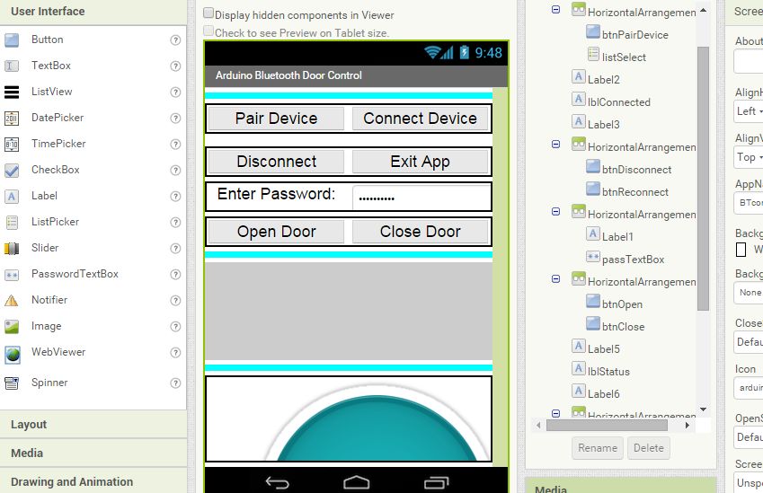
By incorporating these improvements, we aim to provide a seamless and efficient user experience, ensuring that all the new functionalities are easily accessible and user-friendly.
Next Steps
Despite the complexity, I'm proud of what we've accomplished. We've created a system that's not only functional but also secure and user-friendly. And with the sequence diagram, we can see exactly how all the different components fit together to create a seamless user experience.
So what's next? Well, now that we have a complete system including hardware and software, it's time to test it out and see how it works in practice. You could download the whole project source code and test if yourself. Keep in mind that the UI is urgly as I am not ready to spend time on it.
And then, of course, there's the possibility of adding even more features to the system. Maybe we could add support for multiple doors or integrate with other smart home devices. The possibilities are endless, and I'm excited to see where this project will take us in the future.
Questions And Limitations
Relay Connection Conundrum: NO or NC?
Initially, I connected the output wires to the common and NO (Normally Open) side of the relay, assuming it was the correct configuration. My reasoning was that the switch would be voltage-free initially, and then we would apply voltage to it.
The App's Unexpected Behavior
Interestingly, the app now briefly disconnects the switch and then reconnects it to the NC side. This is the opposite of what I initially expected, but fortunately, the app and all switches now work seamlessly together.
The current version of the app lacks robust error handling, which may result in crashes when an error occurs. In such cases, restarting the app usually resolves the issue. Future updates will include more comprehensive error handling to minimize unexpected behavior and improve overall stability.
The MTU Size
For this tutorial, the MTU (Maximum Transmission Unit) is set to a fixed value of 32. Extensive testing has shown that this value offers the best compatibility across different Bluetooth hardware. However, MTU sizes can vary between devices, as they are often determined by the hardware manufacturers. While setting the MTU to a smaller value enhances compatibility, it can also result in slower data transmission rates. This trade-off ensures the app works with as many devices as possible.
More General DIY Hardware
Although the hardware used in this tutorial is based on an existing courtyard gate system, both the hardware and software solutions are designed to be versatile. For those interested in creating their own DIY hardware, you can use components such as an Arduino, Bluetooth Module HC-05, an MCU chip, and a 3D printed door lock. By assembling these parts, you can create a cost-effective DIY smart door lock system.
Here are the source codes for EaseLock, click to download it directly.
- EaseLock Simple Lock: Door Controller
- EaseLock Simple Lock: BTFinder
- EaseLock Command TestSuite
- EaseLock Awesome Lock: Door Controller
- EaseLock Awesome Lock: BTApp


